Multiple and variably-spaced intermediate flow mixing vane grids for fuel assembly

Inactive Publication Date: 2007-09-06
WESTINGHOUSE ELECTRIC CORP
View PDF11 Cites 39 Cited by
  • Summary
  • Abstract
  • Description
  • Claims
  • Application Information

AI Technical Summary

Benefits of technology

[0012] These needs, and others, are met by the present invention which provides multiple IFMs between adjacent structural support grids at the upper end of the fuel assembly. The use of an IFM between adjacent structural support grids increases fuel assembly heat transfer, reduces the risk of CIPS and/or fuel rod corrosion, increases CHF performance, and reduces the risk of grid-to-rod fretting. Generally, the invention provides for an increase in the

Problems solved by technology

That is, as the axial power profile is non-uniform, the coolant hea

Method used


Image

  • Multiple and variably-spaced intermediate flow mixing vane grids for fuel assembly
  • Multiple and variably-spaced intermediate flow mixing vane grids for fuel assembly
  • Multiple and variably-spaced intermediate flow mixing vane grids for fuel assembly

Examples


Embodiment Construction

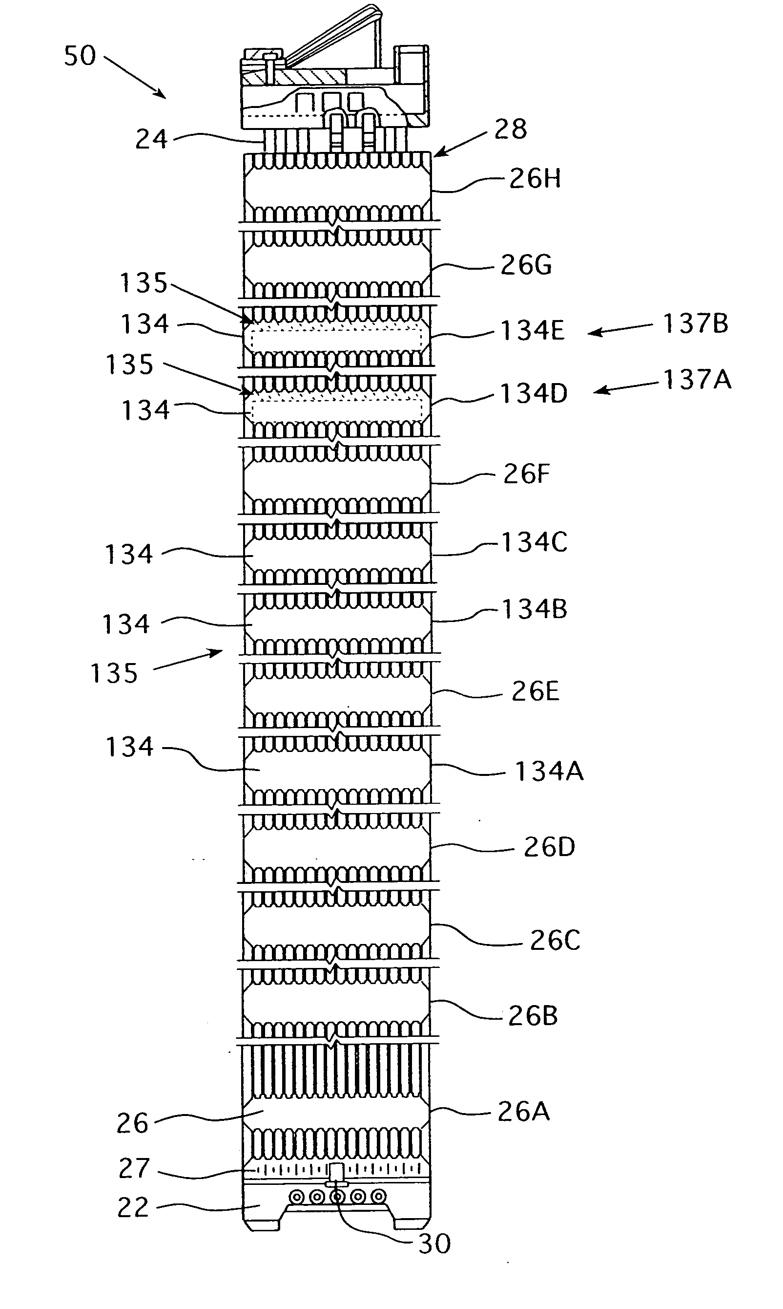
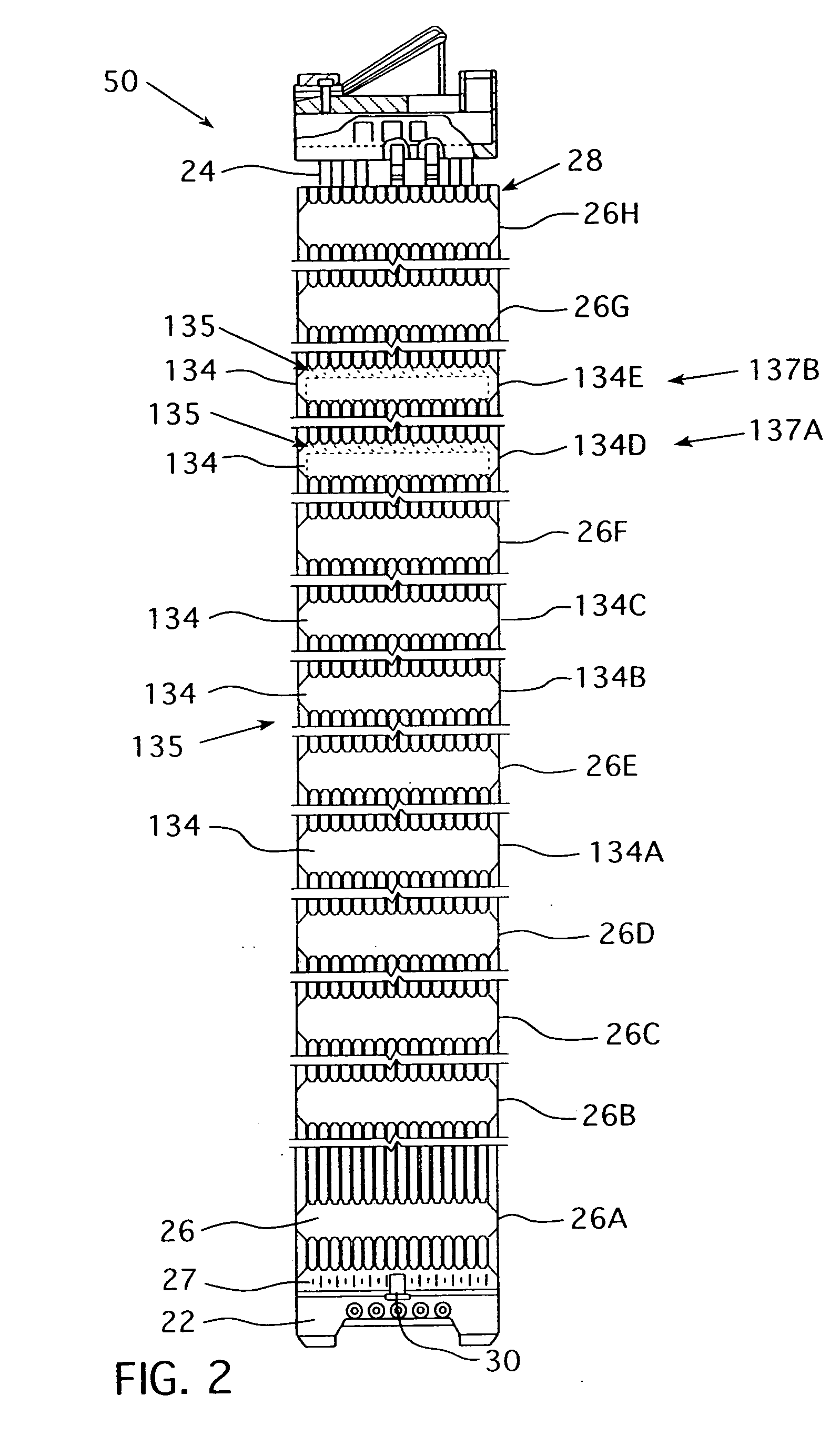
[0018] As used herein, a “mixing device” is a vane, or other structure that creates turbulence in, or effects the direction of, the generally upward flow of the coolant.

[0019] As used herein “spaced unevenly” indicates that in a series of three or more grids, support and / or Intermediate Flow Mixing, at least one grid in the series is closer to one grid in the series than to another grid in the series.

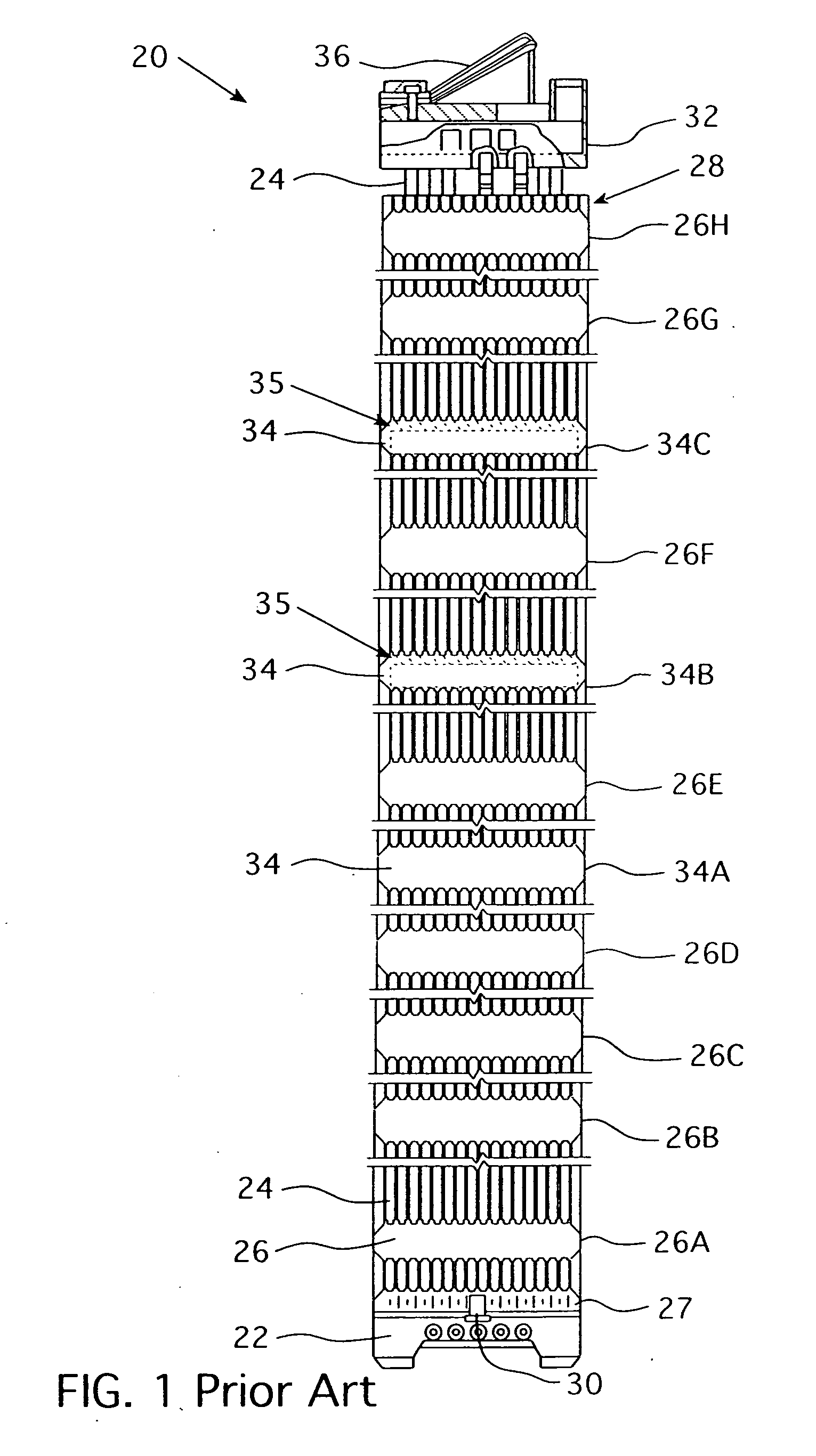
[0020] A prior art fuel assembly 20 for a nuclear reactor is shown in FIG. 1. The fuel assembly 20 is disposed in a water vessel (not shown) having an inlet at the bottom and an outlet at the top. The fuel assembly 20 comprises a lower end structure or bottom nozzle 22 for supporting the fuel assembly 20 on the lower core plate (not shown) in the core region of a reactor (not shown); a number of longitudinally extending control rod guide tubes, or thimbles 24, projecting upwardly from the bottom nozzle 22; a plurality of transverse support grids 26 axially spaced along the guide thimb...


PUM


Abstract

A fuel assembly for a pressurized water reactor that includes a bottom nozzle, a plurality of elongated guide thimbles projecting upwardly from the bottom nozzle, an array of fuel rods, a plurality of support grids axially spaced along the guide thimbles, and at least two Intermediate Flow Mixing grids, which may have different configurations of mixing device formations, disposed between pairs of non-uniformly spaced, adjacent support grids at selected locations.

Description

BACKGROUND OF THE INVENTION [0001] 1. Field of the Invention [0002] The present invention relates to nuclear fuel assemblies and, more specifically, to a mixing grid incorporated into a nuclear fuel assembly. [0003] 2. Description of the Prior Art [0004] In a typical pressurized water reactor (PWR), the reactor core is comprised of a large number of generally vertical, elongated fuel assemblies. The fuel assemblies include a frame assembly structured to support a plurality of fuel rods. The fuel assembly includes a top nozzle, a bottom nozzle, a plurality of structural support grids and intermediate flow mixing grids, and a plurality of thimble tubes. The grids are attached to the plurality of elongated thimble tubes which extend vertically between the top and bottom nozzles. The thimble tubes typically receive control rods, plugging devices, or instrumentation therein. A fuel rod includes nuclear fuel, typically, clad in a cylindrical metal tube. Generally, water enters the fuel as...

Claims


Application Information

Patent Timeline
IPC IPC(8): G21C3/34
CPCG21C3/322G21Y2002/201Y02E30/38G21Y2004/30Y02E30/32G21Y2002/304Y02E30/30G21C3/30G21C3/32G21C3/34
Inventor CONNER, MICHAEL E.KAROUTAS, ZESES E.DZODZO, MILORAD B.LIU, BINJOFFRE, PAUL F.PARAMONOV, DMITRY V.SMITH, LEVIE D. III
Owner WESTINGHOUSE ELECTRIC CORP
Why Eureka
Try Eureka