Turbine

a turbine and installation technology, applied in the direction of wind turbines with perpendicular air flow, waterborne vessels, machines/engines, etc., can solve the problems of deteriorating the overall affecting the efficiency of the turbine installation, and the use of conventional materials, so as to improve the temperature resistance of the axial turbine stages, reduce the cost of production, and prevent the maximum permissible material temperature. , the effect of increasing the temperature resistan

Inactive Publication Date: 2007-09-06
ALSTOM TECH LTD
View PDF12 Cites 13 Cited by
  • Summary
  • Abstract
  • Description
  • Claims
  • Application Information

AI Technical Summary

Benefits of technology

[0018] Should the turbine, however, include only axial turbine stages according to a conventional construction, then in this case a plurality of axial turbine stages would be necessary in order to effect the same enthalpy conversion and, consequently, the same lowering of the temperature, as this is effected by the only one radial or diagonal turbine stage. As a consequence, suitable measures would also be adopted for this plurality of axial turbine stages in order to increase the temperature resistance of these axial turbine stages in order to thus prevent a maximum permissible material temperature being exceeded. A turbine, which includes only axial turbine stages, therefore, is significantly more expensive in production when using high heat resistant materials. If the affected components are cooled by a cooling fluid, then, on the one hand, cooling

Problems solved by technology

This leads to temperatures being already achieved today also in steam turbines in which a use of conventional materials, especially for the blading of the turbine, for the flow passage walls and also for the turbine shaft, is no longer possible without temperature reduction measures.
This leads to a deterioration of the overall efficiency of the turbine installation.
Aerodynamic losses are also caused in the case of a film cooling or an effusion cooling of the blades by means of admission of cooling fluid into the main flow of the turbine.
Alternatively, the blades, and partially also the shafts of the turbine, can be produced from high heat-resistant materials, as a result of which, however, the turbine becomes very expensive in production.
As a result of this, it is often very difficult to design such turbine bladings with a good aerodynamic efficiency.
A turbine, which includes only axial turbine stages, therefore, is significantly more expensive in production when using high heat resistant materials.
On the other hand, the efficiency of the turbine is impaired as a result of this.
A plurality of radial or diagonal turbine stages, however, lead again to an increase of the production costs.
As a result of this, the flow path also becomes constructionally more cos

Method used


Image

  • Turbine
  • Turbine
  • Turbine

Examples


Embodiment Construction

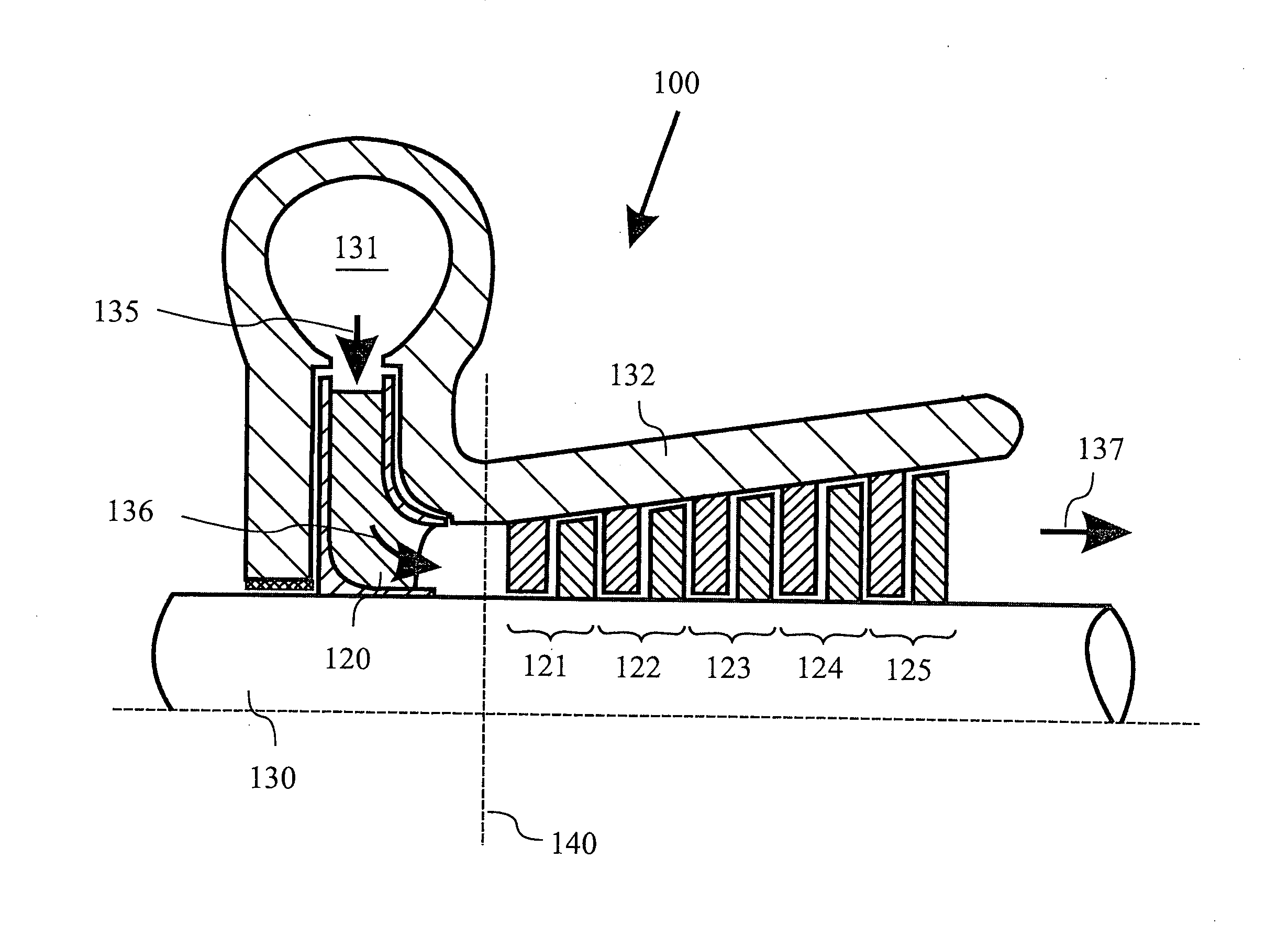
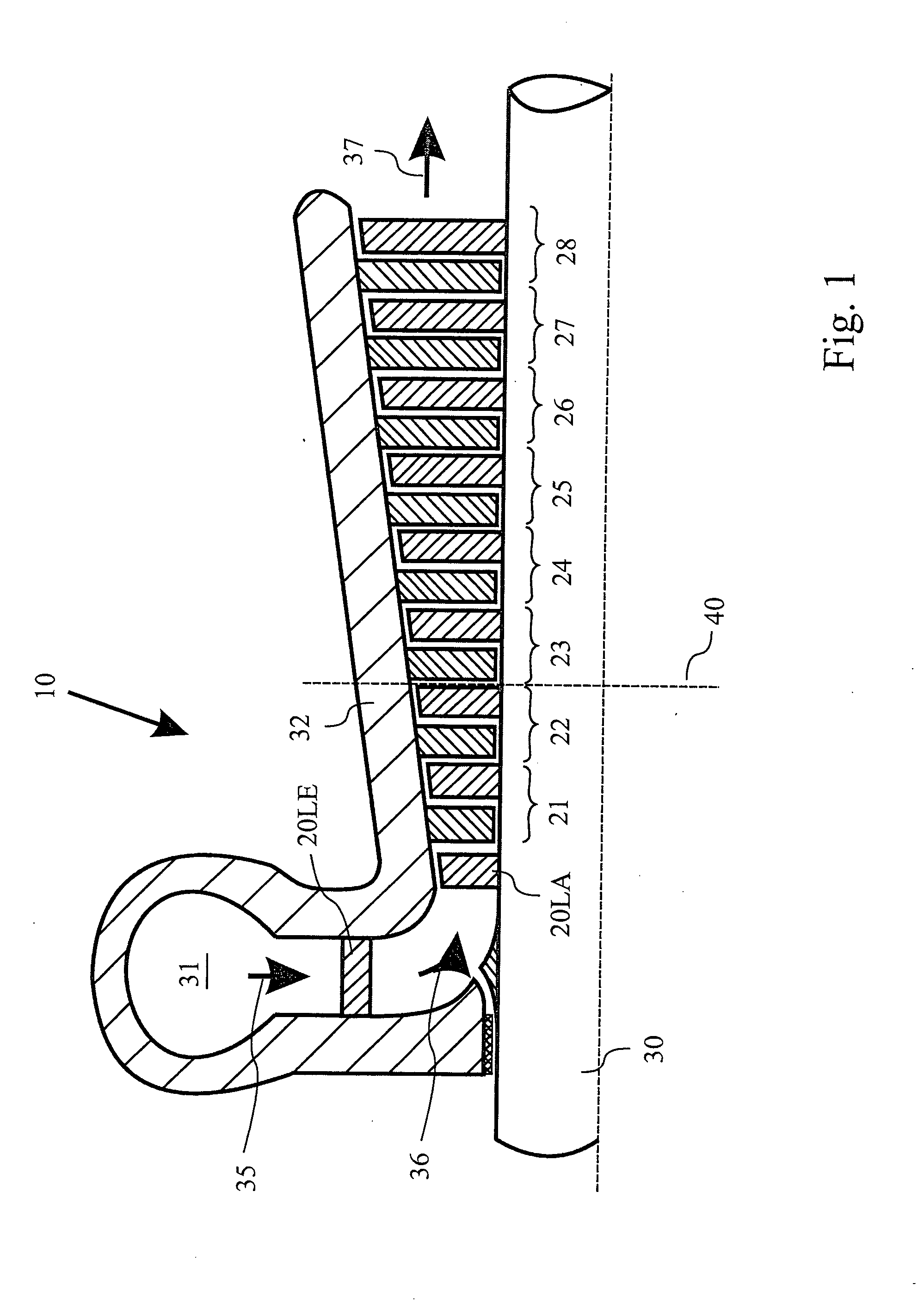
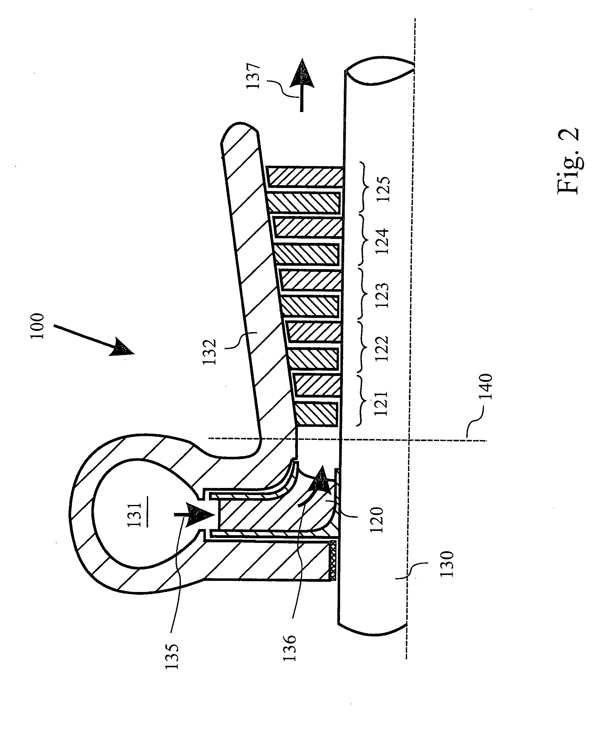
[0044]FIG. 1 shows a turbine 10 which is formed as a high-pressure turbine of a steam turbine installation, which turbine is known from the prior art. The throughflow fluid in this case is steam. The steam which comes from a steam generator (not shown in FIG. 1) is fed radially to the turbine 10 via a live steam inlet branch 31. In the radial inflow section of the live steam inlet branch 31, a first guide wheel 20LE for straightening and / or for pre-swirl generation of the steam flow is to be found here. The steam flow is then deflected in a deflecting section (in the region of the flow arrow 36) from the radial flow direction (direction of the flow arrow 35) into an axial flow direction (direction of the flow arrow 37). Only after deflection into the axial flow direction has been carried out, does the steam-flow flow through the blade wheel 20LA of the first turbine stage and, after this, also through the further axial turbine stages 21-28 of the turbine 10 which are arranged downst...


PUM

PropertyMeasurementUnit
Temperatureaaaaaaaaaa

Abstract

A turbine (100) of a turbine installation, especially a steam turbine of a steam turbine installation, includes at least one radial or diagonal turbine stage (120) with radial or diagonal inflow and axial outflow, and also at least one axial turbine stage (121-125) with axial inflow and axial outflow. The at least one radial or diagonal turbine stage (120) forms the first stage of the turbine (100) and the at least one axial turbine stage (121-125) is arranged downstream of the radial or diagonal turbine stage (121) as an additional stage of the turbine. The at least one radial or diagonal turbine stage (120) has a higher temperature resistance than the at least one axial turbine stage (121-125). The turbine (100) makes it possible to significantly increase the process temperature of the steam turbine installation, wherein measures for increasing the temperature resistance need only to be adopted for components of the radial or diagonal turbine stage (120).

Description

[0001] This application is a Continuation of, and claims priority under 35 U.S.C. § 120 to, International Application Number PCT / EP2005 / 055587, filed 26 Oct. 2005, and claims priority therethrough to Swiss application number 1807 / 04, filed 2 Nov. 2004, the entireties of both of which are incorporated by reference herein.BACKGROUND [0002] 1. Field of Endeavor [0003] The invention relates to a turbine of a turbine installation, especially a steam turbine of a steam turbine installation. In addition, the invention relates to a method for the design of a turbine, and also a method for operating a turbine installation which is equipped with such a turbine. [0004] 2. Brief Description of the Related Art [0005] On account of the continuing efforts towards improvement of the efficiency of modern turbine installations, especially modern steam turbine installations, it appears desirable to increase the process temperature of the turbine installations. An increase of the process temperature es...

Claims


Application Information

Patent Timeline
IPC IPC(8): F01D1/02
CPCF01D1/04F01D1/06Y10T29/4932F05D2220/31F01D5/28
Inventor GREIM, RALFHAVAKECHIAN, SAID
Owner ALSTOM TECH LTD
Why Eureka
Try Eureka