

Fuel cell
- Summary
- Abstract
- Description
- Claims
- Application Information
AI Technical Summary
Benefits of technology
Problems solved by technology
Method used
Image

Examples
first embodiment
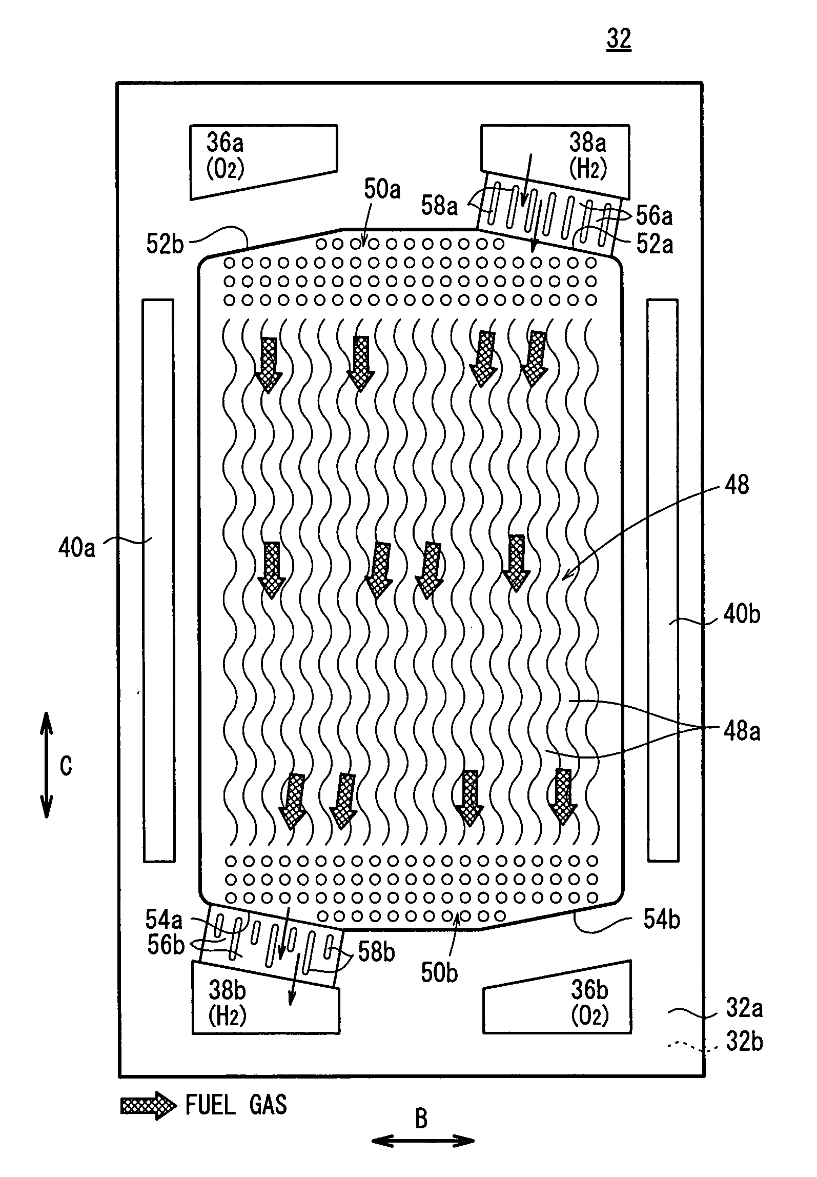
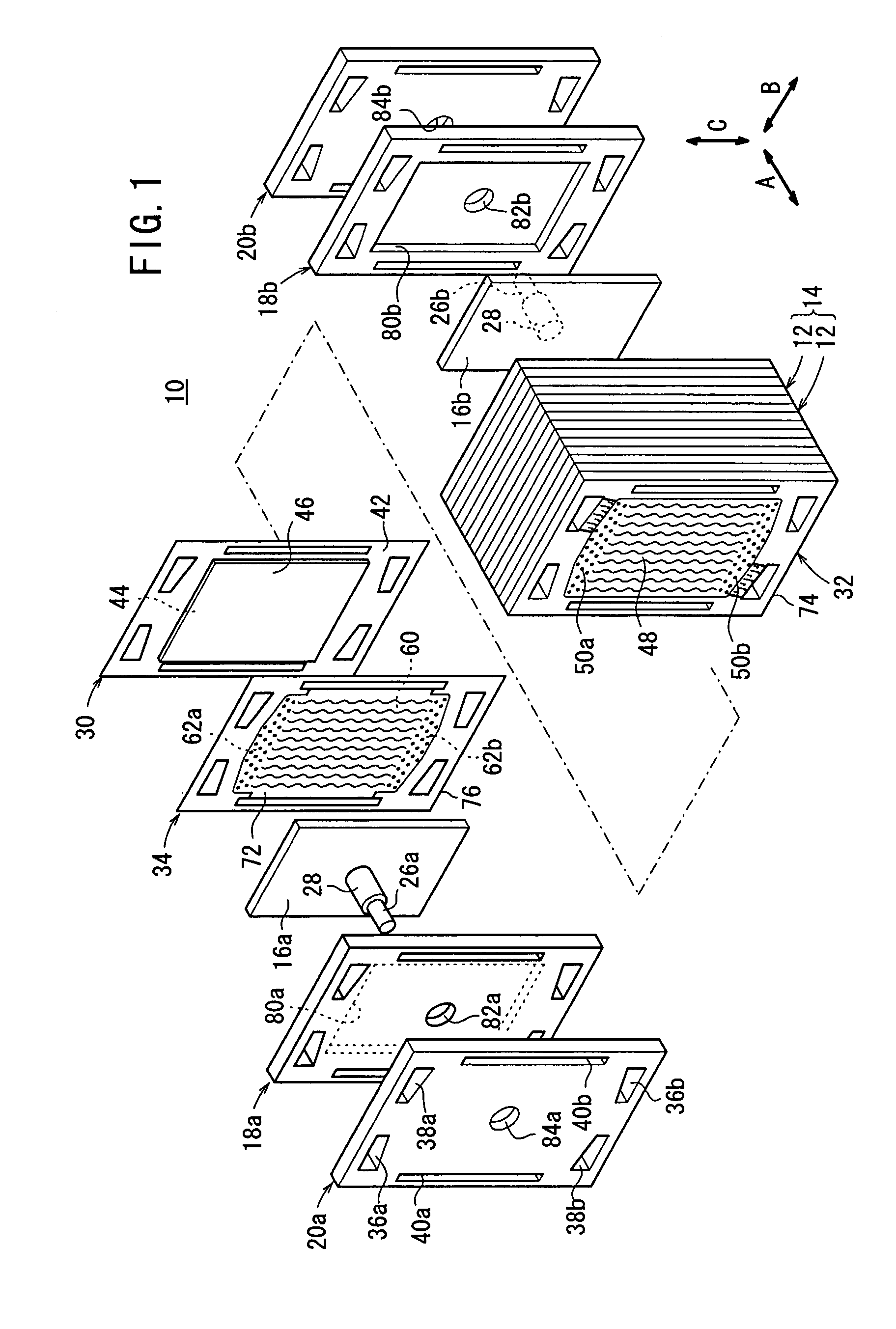
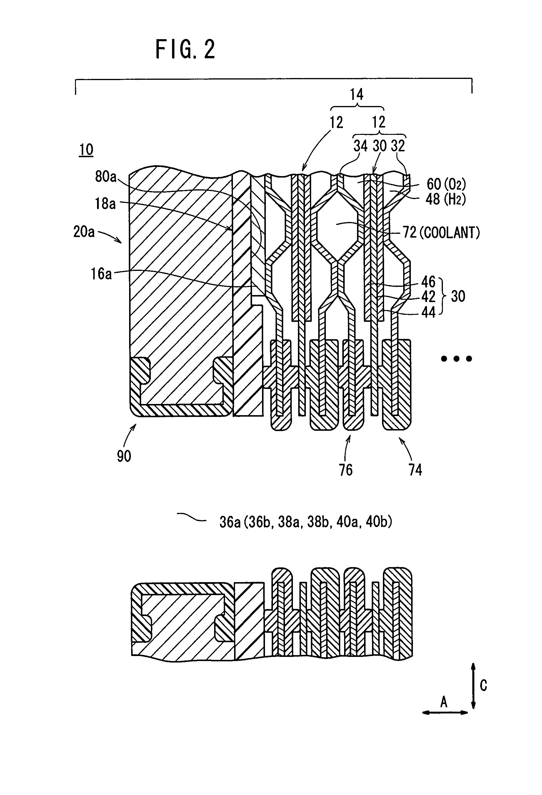
[0025]FIG. 1 is a partial exploded perspective view showing a fuel cell stack (fuel cell) 10 according to the present invention. FIG. 2 is a partial cross sectional view showing the fuel cell stack 10.
[0026]The fuel cell stack 10 includes a stack body 14 formed by stacking a plurality of unit cells 12 in a substantially horizontal direction indicated by an arrow A. At one end of the stack body 14 in the stacking direction, a terminal plate 16a is provided. An insulating plate 18a is provided outside the terminal plate 16a, and an end plate 20a is provided outside the insulating plate 18a.
[0027]At the other end of the stack body 14 in the stacking direction, a terminal plate 16b is provided. An insulating plate 18b is provided outside the terminal plate 16b, and an end plate 20b is provided outside the insulating plate 18b (see FIG. 1). For example, the fuel cell stack 10 is integrally held in a box-shaped casing (not shown) including the end plates 20a, 20b having a rectangular sha...
third embodiment
[0071]In the third embodiment, the fuel gas flow field 112 is formed by the wavy ridges 112a, and the lower ends of the wavy ridges 112a are arranged in a zigzag pattern. Therefore, when the water produced in the power generation reaction moves downwardly along the wavy ridges 112a by its own weight, the water is not retained in the fuel gas flow field 112 as water droplets, and the water is smoothly discharged into the outlet buffer 50b. The lower end of the wavy ridge 112a has a curved end surface (R-surface). In the structure, it is possible to further reliably prevent the water droplets from being kept at the lower end of the wavy ridge 112a.
PUM
 Abstract
Description
Claims
Application Information