
Superimposed Steering System for a Vehicle

a steering system and superimposed technology, applied in the direction of steering parts, road vehicles, ball bearings, etc., can solve the problems of uncomfortable steering or driving sensation for drivers, and the abovedescribed variable ratio gear unit with servomotor is relatively complicated and expensive in technical terms. achieve the effect of simple construction, low installation space, and comfortable handling

Inactive Publication Date: 2007-09-13
ROBERT BOSCH AUTOMOTIVE STEERING
View PDF8 Cites 17 Cited by
  • Summary
  • Abstract
  • Description
  • Claims
  • Application Information

AI Technical Summary

Benefits of technology

[0007] Example embodiments of the present invention may provide a playfree superimposed steering system for a vehicle, which superimposed steering system may provide comfortable handling, may have a simple construction and the installation space for which may be minimized.
[0012] In order to simplify the assembly of the harmonic drive and in order for it to be possible for individual components to be exchanged rapidly, the first gear unit input shaft is connected releasably to the eccentric flexspline. In addition, this may provide that the individual components of the harmonic drive may be formed from different materials and conventional manufacturing methods may continue to be usable for the components. In order to improve the operating comfort of the steering system, there is provision for the torque of the servomotor to be supported on a component, fixed to the vehicle, of the steering system or the vehicle, which is not the steering column itself.
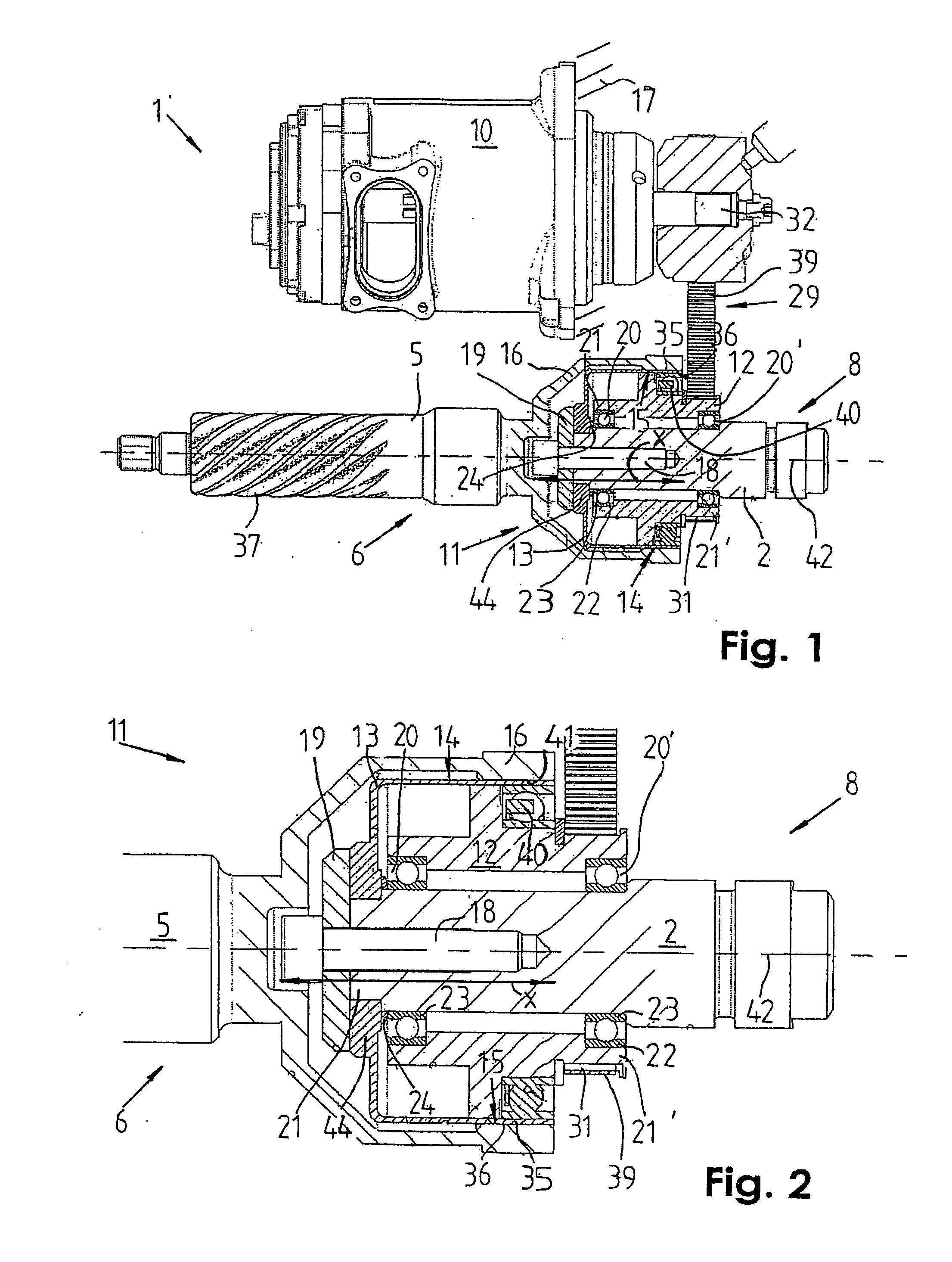
[0013] The radially flexible flexspline may be fixed in a form-fitting and releasable manner on the first gear unit input shaft, for simple assembly and possible maintenance-induced dismantling with the aid of a connecting element, such as a threaded bolt. A clutch plate which brings about a form-fitting connection which is fixed in terms of rotation is arranged or clamped between the radially flexible flexspline and the first gear unit input shaft. The clutch plate engages with latching elements in a form-fitting manner into the first gear unit input shaft and the radially flexible flexspline. The eccentric drive core which is connected fixedly in terms of rotation to a shaft of the servomotor is mounted rotatably on the first gear unit input shaft via roller bearings at its axial ends.
[0014] The eccentric drive core is arranged radially between the first gear unit input shaft and the radially flexible flexspline and is configured to be as compact as possible radially in order to reduce the installation space requirement of the steering system.
[0015] The eccentric drive core may engage axially over a large part into the radially flexible flexspline and into the, e.g., bell-shaped circular spline. This may result in an axially and radially compact construction of the harmonic drive and the steering system. The eccentric drive core rolls with a flexible ball bearing in the radially flexible flexspline and deforms the latter in a continuously changing manner. Here, as a function of the cross-sectional shape of the drive core, one or more circumferential sections of the outer circumferential surface of the radially flexible flexspline are in engagement with a substantially cylindrical supporting surface of the circular spline. The circular spline surrounds the flexspline radially. As the circumference of the outer circumferential surface of the radially flexible flexspline is shorter than the circumference of the cylindrical supporting surface of the circular spline, the circular spline, and thus also the gear unit output shaft, rotates by this length difference, the gear unit output shaft being connected fixedly in terms of rotation to the circular spline and in turn being connected to the input shaft of the steering gear. As a result, it is possible for an additional steering angle in the positive or negative direction with respect to the steering angle which is input on the steering handle to be applied with great precision to the circular spline and the gear unit output shaft.
[0020] The overall construction of the superimposed steering system makes it possible for current to be supplied and / or signals to be forwarded between the components of the steering system without additional current guiding devices such as sliders or flat spiral springs, etc. This may result in an increase in the operational reliability of the steering system.

Problems solved by technology

This results in gear unit play which can produce undesirable steering play.
In addition, the abovedescribed variable ratio gear units with servomotor are relatively complicated and expensive in technical terms.
Although an additional angle is superimposed with this superimposed steering system on a rotational movement between the steering wheel and the steering gear, the opposing torque of the electric servomotor drive is supported on the steering column shaft, which can lead to an uncomfortable steering or driving sensation for a driver.
This may result in an axially and radially compact construction of the harmonic drive and the steering system.
This may result in an increase in the operational reliability of the steering system.

Method used


Image

  • Superimposed Steering System for a Vehicle
  • Superimposed Steering System for a Vehicle
  • Superimposed Steering System for a Vehicle

Examples


Embodiment Construction

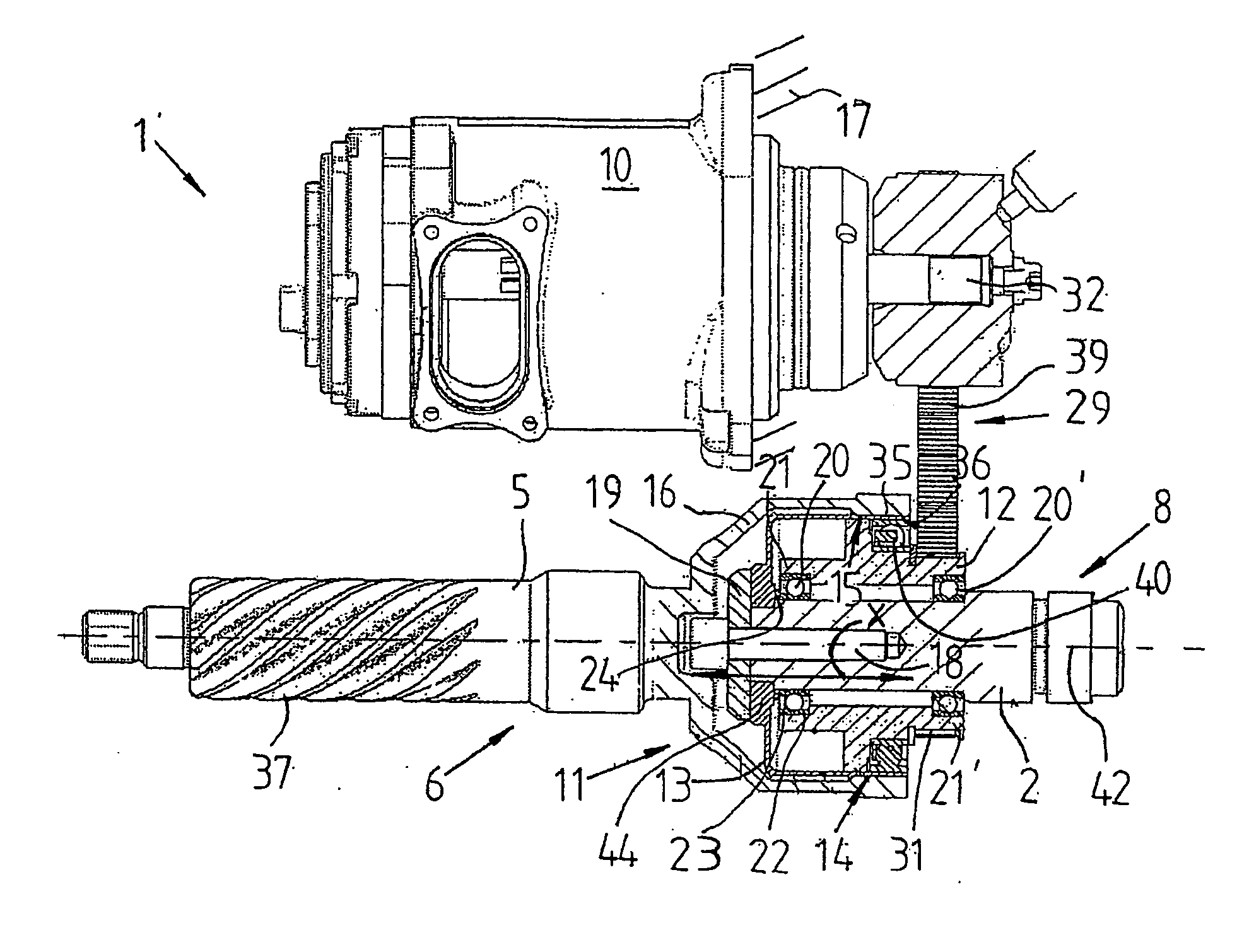
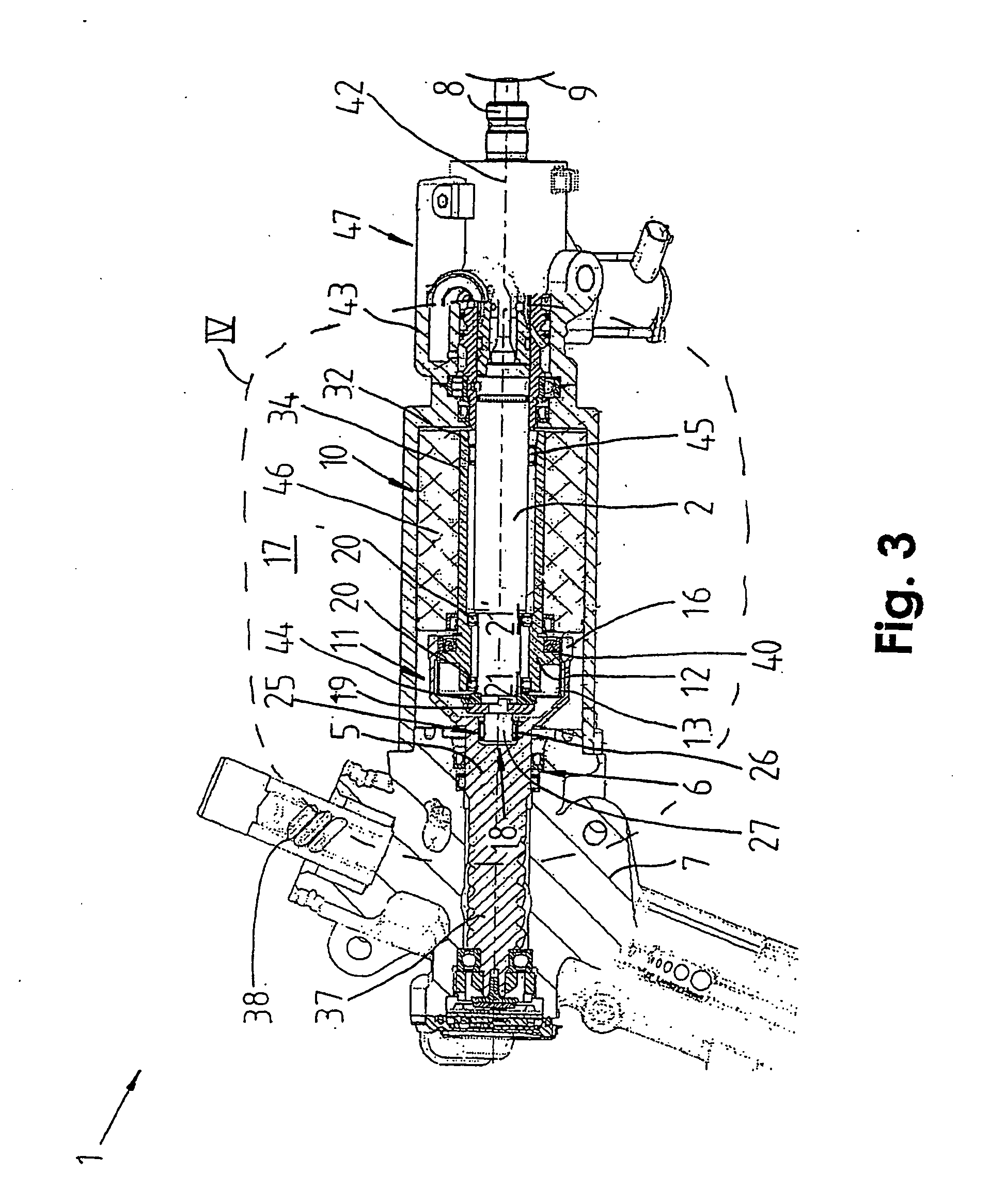
[0029]FIG. 1 illustrates a superimposed steering system 1 for a vehicle which is configured as active steering, in a plan view and a partial longitudinal cross-sectional view. The superimposed steering system 1 is formed as an electric superimposed steering system from a servomotor 10 which is supported on a component 17 which is fixed to the vehicle and is not the steering column of the vehicle, from a steering shaft 8 which is connected fixedly in terms of rotation to a steering handle 9, from a variable ratio gear unit 4 which is configured as a harmonic drive 11, and from an input shaft 6 for a steering gear 7. The steering gear 7 may be part of an electric or hydraulic power assistance steering system.

[0030] In the exemplary embodiment illustrated, the steering gear 7 includes a helically toothed pinion 37 which is arranged at one axial end of the input shaft 6, and a rack 38 which is mounted so as to be axially displaceable and with which the pinion 37 meshes. The rack 38 is ...


PUM


Abstract

A superimposed steering system for a vehicle, e.g., a servo-assisted or power steering system for a motor vehicle, includes a differential drive, which is configured as a shaft drive and has a first input shaft and a second input shaft, for superimposing the rotational angles that occur in the first and second input shafts on an output shaft of the differential drive. The output shaft acts on an input shaft of a steering gear. The first input shaft interacts with a steering handle by a steering shaft and the second input shaft interacts with a servo motor. A superimposed steering system may apply an additional steering angle, without play, to the output shaft and may have a simple, cost-effective, space-saving construction, while being easy to install. The first input shaft is directly connected in a detachable manner to a radially flexible flex-spline of the shaft drive, the first input shaft passing through an eccentric drive core of the shaft drive, which extends into the radially flexible flex spline.

Description

FIELD OF THE INVENTION [0001] The present invention relates to a superimposed steering system for a vehicle, e.g., a power steering system or a power assistance steering system for a motor vehicle. BACKGROUND INFORMATION [0002] Certain superimposed steering systems are conventional and an aspect of which is that, if required, a further rotational angle can be superimposed by an actuator on the steering angle which is selected on a steering handle by a driver of a vehicle. The additional rotational angle is controlled by an electronic control and / or regulating device and serves to increase the driving stability of the vehicle or other purposes. [0003] In order to produce an additional angle or a further rotational angle, it is described in German Published Patent Application No. 101 29 450 and German Published Patent Application No. 101 60 313 to use a planetary gear mechanism as variable ratio gear unit, a steering shaft which is connected to a first gear unit input shaft being disc...

Claims


Application Information

Patent Timeline
IPC IPC(8): B62D5/04B62D5/00
CPCB62D5/008B62D5/0415B62D5/0412F16C2326/24F16C19/06B62D5/04B62D5/00
Inventor KRUTTSCHNITT, ANDREASRUPP, ARTHUR
Owner ROBERT BOSCH AUTOMOTIVE STEERING
Learn More