Radiation imaging apparatus and radiation imaging system

a radiation imaging and apparatus technology, applied in the field of radiation imaging apparatus and radiation imaging system, can solve the problems of complex algorithm, increased apparatus development and cost, inability to adjust, etc., and achieve the effect of reducing production yield, increasing the cost of apparatus configuration, and consuming more time for processing output signals

Inactive Publication Date: 2007-09-13
CANON KK
View PDF28 Cites 76 Cited by
  • Summary
  • Abstract
  • Description
  • Claims
  • Application Information

AI Technical Summary

Benefits of technology

[0014]In U.S. Pat. No. 6,734,414, since the drive wiring is randomly connected, output signals are irregular and the output signals need to be rearranged at a processing circuit of a rear stage, consuming more time for processing the output signals and leading to increase in the cost of apparatus configuration. Furthermore, the connection of the drive wirings is complicated, which may lower production yield to increase production cost.
[0016]The present invention has been made in view of the problems and has its purpose to provide a radiation imaging apparatus and a radiation imaging system which realize reducing an extremely conspicuous line noise generated on an image with a relatively simple configuration.
[0018]According to the present invention, an extremely conspicuous line noise generated on an image can be reduced with a relatively simple configuration. Furthermore, according to the present invention, particularly in the moving image radiographing, reading the addition of the pixel signals increases a frame rate and signal quantity thereof, enabling generating a high-speed moving image which is low in line noise. In addition, only a single radiation imaging apparatus enables both still and moving image radiographing. The present invention achieves an effect that reduces the line noise without increasing cost.

Problems solved by technology

However, particularly in the X-ray imaging apparatus with an area of as large as 40 cm×40 cm, the line noises generated on a line basis probably have shading and show an inappropriate correction value as a line noise quantity to be corrected.
Using a calculation method taking the above into consideration causes a problem that a real-time correction is difficult if it takes a long time to perform calculation.
In addition, a complicated algorithm increases a burden to apparatus development and a cost.
In U.S. Pat. No. 6,734,414, since the drive wiring is randomly connected, output signals are irregular and the output signals need to be rearranged at a processing circuit of a rear stage, consuming more time for processing the output signals and leading to increase in the cost of apparatus configuration.
Furthermore, the connection of the drive wirings is complicated, which may lower production yield to increase production cost.
That is to say, it has been difficult for the conventional art to realize reducing an extremely conspicuous line noise generated on an image without a substantial increase in cost and with a relatively simple configuration.
Especially in a moving image radiographing (fluoroscopy) mode with a little dose of X ray quantity, it has been very difficult to reduce the line noise with a relatively simple configuration.

Method used


Image

  • Radiation imaging apparatus and radiation imaging system
  • Radiation imaging apparatus and radiation imaging system
  • Radiation imaging apparatus and radiation imaging system

Examples


first embodiment

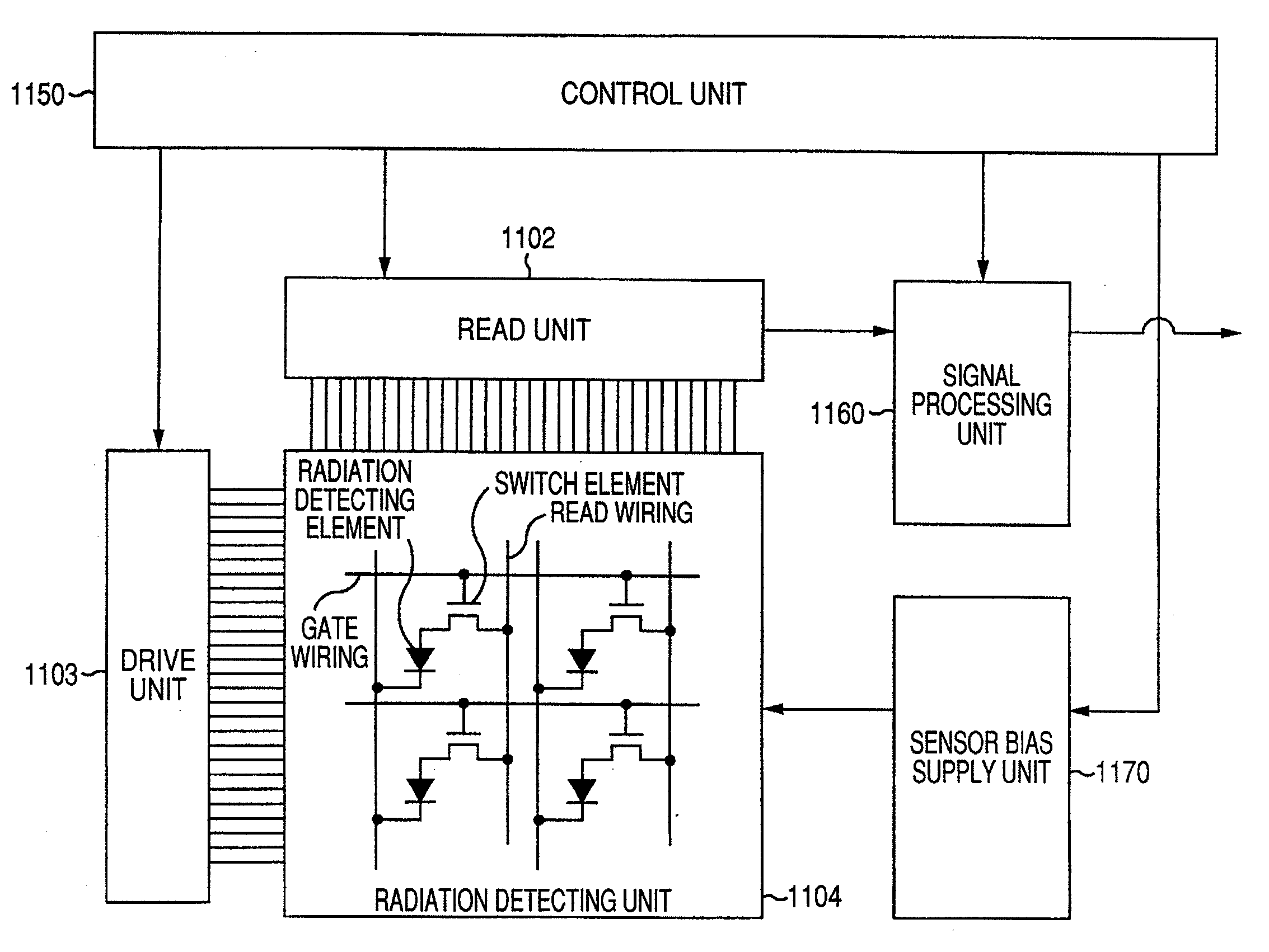
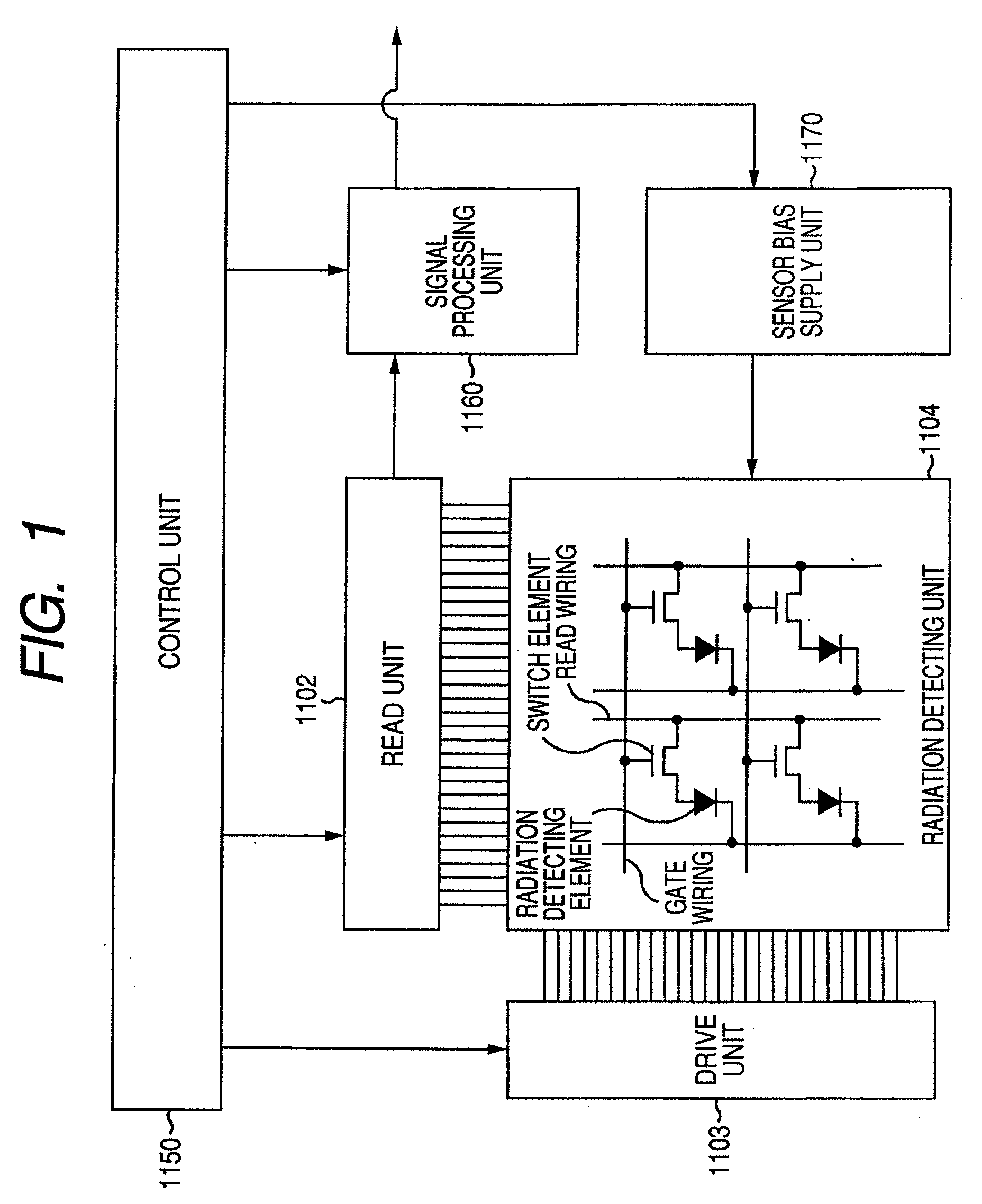
[0044]FIG. 1 is a schematic block diagram of a radiation imaging apparatus according to a first embodiment.

[0045]The radiation imaging apparatus according to the first embodiment includes a read unit 1102, drive unit 1103, radiation detecting unit 1104, control unit 1150, signal processing unit 1160 and sensor bias supply unit (voltage supply unit) 1170.

[0046]The radiation detecting unit 1104 includes radiation detecting elements, switch elements, drive wirings and signal wirings and detects incident radiations such as X rays to convert them into signal charges. The drive unit 1103 drives the switch elements of the radiation detecting unit 1104 when electric signals based on signal charges in the radiation detecting elements of the radiation detecting unit 1104 are read. The read unit 1102 reads the electric signals based on the signal charges in the radiation detecting elements of the radiation detecting unit 1104.

[0047]The signal processing unit 1160 provides various processes for...

second embodiment

[0077]FIG. 10 is a timing chart illustrating an example of operation of the radiation imaging apparatus according to a second embodiment.

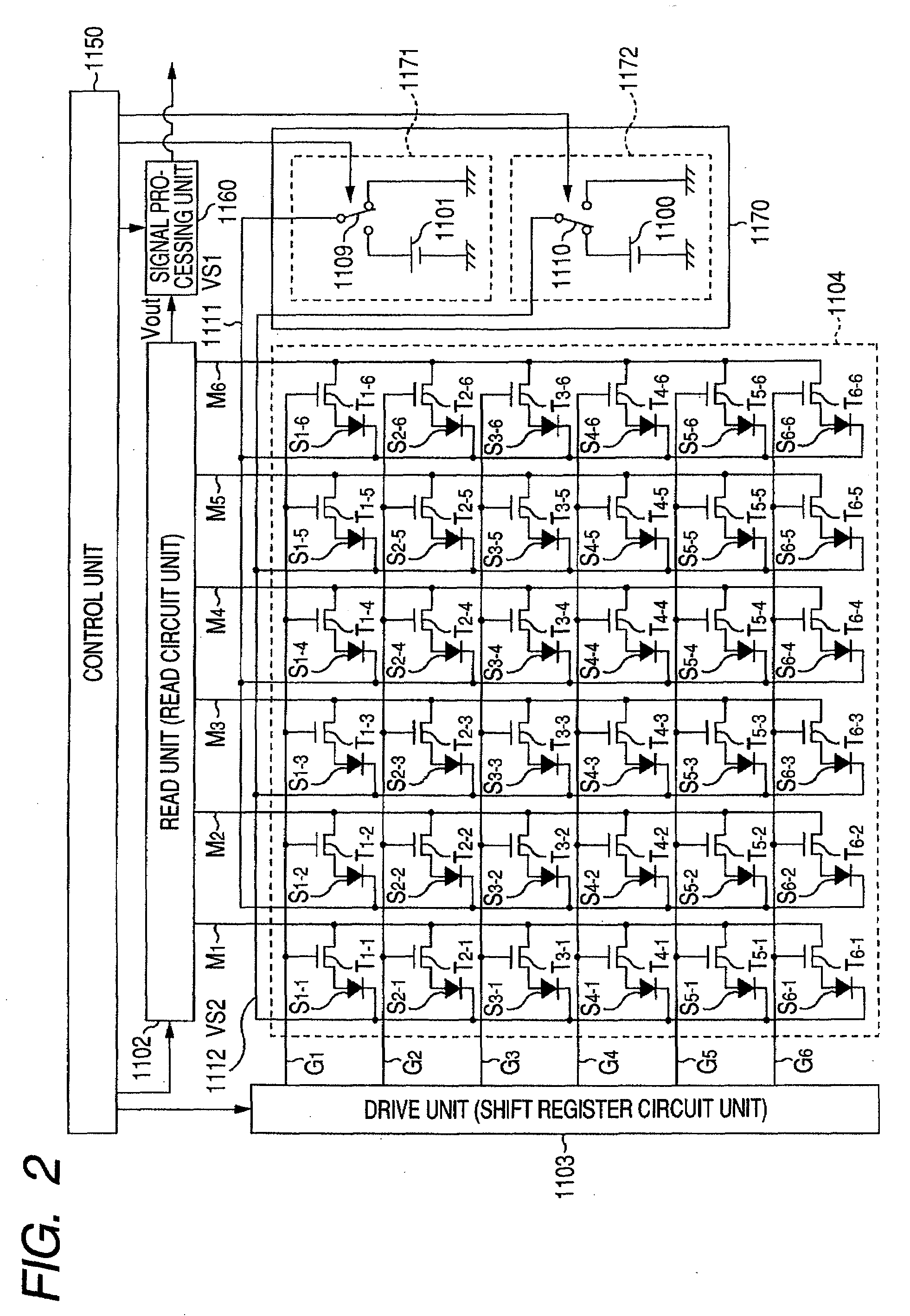
[0078]In the second embodiment, as is the case with the first embodiment, the radiation detecting elements in the odd columns are made sensible state and the radiation detecting elements in the even columns are made senseless state by the control of the control unit 1150. Thus, also in FIG. 10, Vout representing the output of the analog signal from the read circuit unit 1102 is output every other pixel or only the signals in the radiation detecting elements in the odd columns are output. As illustrated in FIG. 5, in the second embodiment, the drive circuit (shift register circuit unit) 1103 provides such a control as to simultaneously input drive signals into two drive wirings. This causes the read circuit unit 1102 to read the addition of the electric signals in the first and the second line, the addition of the electric signals in the third and t...

third embodiment

[0084]FIG. 12 is a schematic circuit diagram of a radiation imaging apparatus according to a third embodiment. In FIG. 12, the same composing elements as in FIG. 2 are given the same reference characters. In addition, 36 (six times six) pixels are illustrated to simplify the description hereinafter.

[0085]FIG. 12 is different from FIG. 2 in the connection of the bias lines VS1 and VS2 to the radiation detecting elements in the radiation detecting unit 1104. More specifically, in FIG. 12, the first bias line VS1 (1111) is connected to the radiation detecting elements S1-1 to S6-1 in the first column and the second bias line VS2 (1112) is connected to the radiation detecting elements in the second to the sixth columns. In FIG. 12, a voltage (first voltage) relative to GND is applied across the radiation detecting elements in the first column from the first power source unit 1171 and a voltage (second voltage) relative to the power source 1101 is applied across the radiation detecting e...


PUM


Abstract

A radiation imaging apparatus comprises a read unit reading the electric signal in the radiation detecting elements in a radiation detecting unit comprises the radiation detecting elements converting incident radiation into electric signals arranged two-dimensionally, a control unit controlling the radiation detecting unit with such that a first radiation detecting element group is made senseless state and a second radiation detecting element group is made sensible state, and a signal processing unit performing a subtraction processing such that the electric signal in the radiation detecting elements made senseless state read by the read unit is subtracted from the electric signal in the radiation detecting elements made sensible state read by the read unit according to the state control by the control unit, to reduce conspicuous line noise in an image by a relatively simple configuration.

Description

BACKGROUND OF THE INVENTION[0001]1. Field of the Invention[0002]The present invention relates to a radiation imaging apparatus and a radiation imaging system suitably applicable to medical diagnosis and industrial non-destructive inspection. In the description of the specification, a radiation includes electromagnetic waves such as X- and gamma rays and alpha and beta rays.[0003]2. Description of the Related Art[0004]Nowadays, X-ray imaging in a hospital has been changing from a conventional analog system using films to a digital system. Digitized X-ray imaging easily solves problems which have been pointed out so far such as the safekeeping of films, the management of developers, radiographing time period and burden to patients at the time of failure in radiographing and enables providing a new medial environment to meet the needs of the times.[0005]A CR (computed radiography) system using photostimulable phosphor called an imaging plate (IP) as a digital X-ray imaging system has d...

Claims


Application Information

Patent Timeline
Patent Type & Authority Applications(United States)
IPC IPC(8): G01T1/24G01T1/20H04N5/32H04N5/335H04N5/341H04N5/357H04N5/369H04N5/374H04N5/376
CPCH04N5/32H04N5/3658G01T7/005G01T1/247H04N5/374H04N25/677H04N25/76
Inventor ENDO, TADAOKAMESHIMA, TOSHIOYAGI, TOMOYUKITAKENAKA, KATSUROYOKOYAMA, KEIGO
Owner CANON KK
Why Eureka
Try Eureka