Discharge lamp lighting apparatus, luminaire and illumination system

a technology of lighting apparatus and discharge lamp, which is applied in the direction of electric variable regulation, process and machine control, instruments, etc., can solve the problems of large investment in development cost and development term, and achieve the effects of preventing deterioration in start characteristic and life, reducing production cost, and reliably performing load discrimination

Inactive Publication Date: 2007-09-13
MATSUSHITA ELECTRIC WORKS LTD
View PDF7 Cites 34 Cited by
  • Summary
  • Abstract
  • Description
  • Claims
  • Application Information

AI Technical Summary

Benefits of technology

[0019] By use of the high-intensity discharge lamp lighting apparatus according to the first aspect of the present invention, it is possible to discriminate a plurality of types of lamp rated power without applying stress to the lamps irrespective of states (initial start, restart) of the lamps so that storage of only one type of high-intensity discharge lamp lighting apparatus is required in production of a luminaire thereby to reduce production cost. Further, it is possible for a user to replace the lamps as usage.
[0020] According to the second aspect of the present invention, in the discharge lamp lighting apparatus capable of lighting a plurality of discharge lamps with rated power and further capable of automatically discriminating rated power of the discharge lamps t

Problems solved by technology

Namely, it has been necessary to set high-intensity discharge lamp lighting apparatuses exclusively for the respective discharge lamps with d

Method used


Image

  • Discharge lamp lighting apparatus, luminaire and illumination system
  • Discharge lamp lighting apparatus, luminaire and illumination system
  • Discharge lamp lighting apparatus, luminaire and illumination system

Examples


embodiment 1

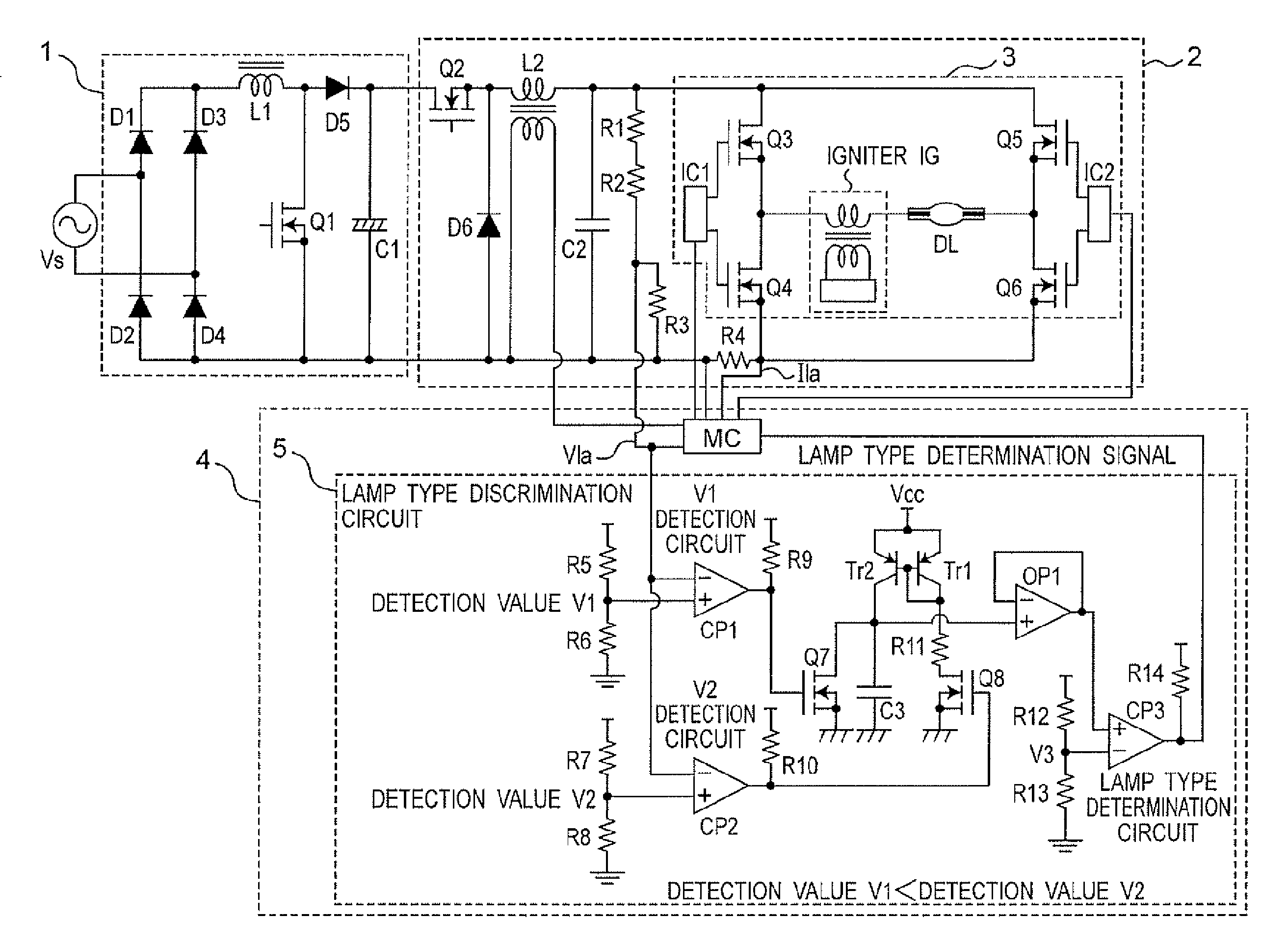
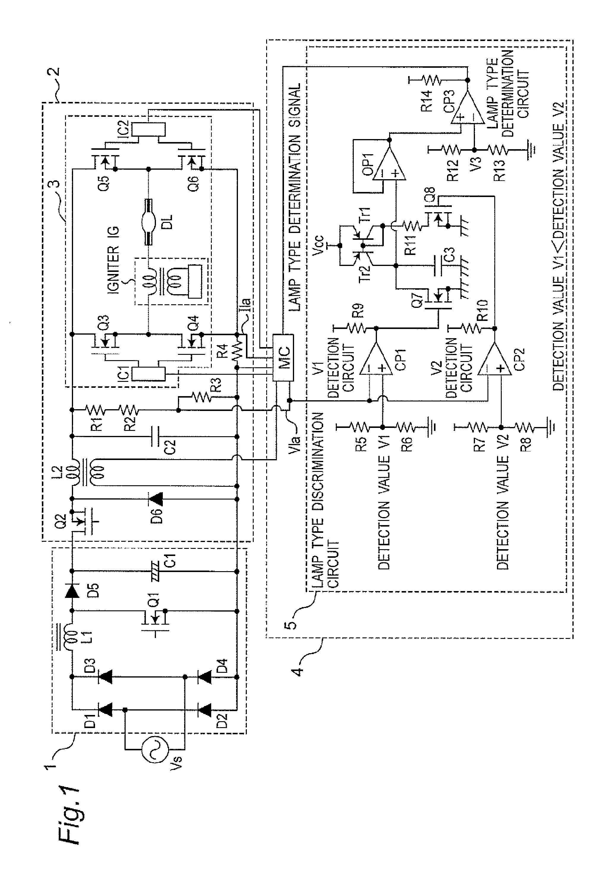
[0094]FIG. 1 shows a circuit diagram of a high-intensity discharge lamp lighting apparatus according to Embodiment 1 of the present invention. A configuration of the circuit is described below. A DC power source circuit section 1 including a rectification smoothing circuit and the like is connected to a commercial AC power source Vs. The DC power source circuit section 1 includes a full wave rectification circuit composed of diodes D1 to D4, a chopper circuit which switches the full wave rectification output for voltage boosting, and a smoothing capacitor C1 which charges the boosted DC voltage. An inductor L1, a switching element Q1 and a diode D5 constitute the step-up chopper circuit which has a function of reducing a down-period of an input current from the commercial AC power source Vs to improve an input current distortion rate.

[0095] A power conversion circuit section 2 capable of adjusting and controlling a supply power to be supplied to the discharge lamp is connected to t...

embodiment 2

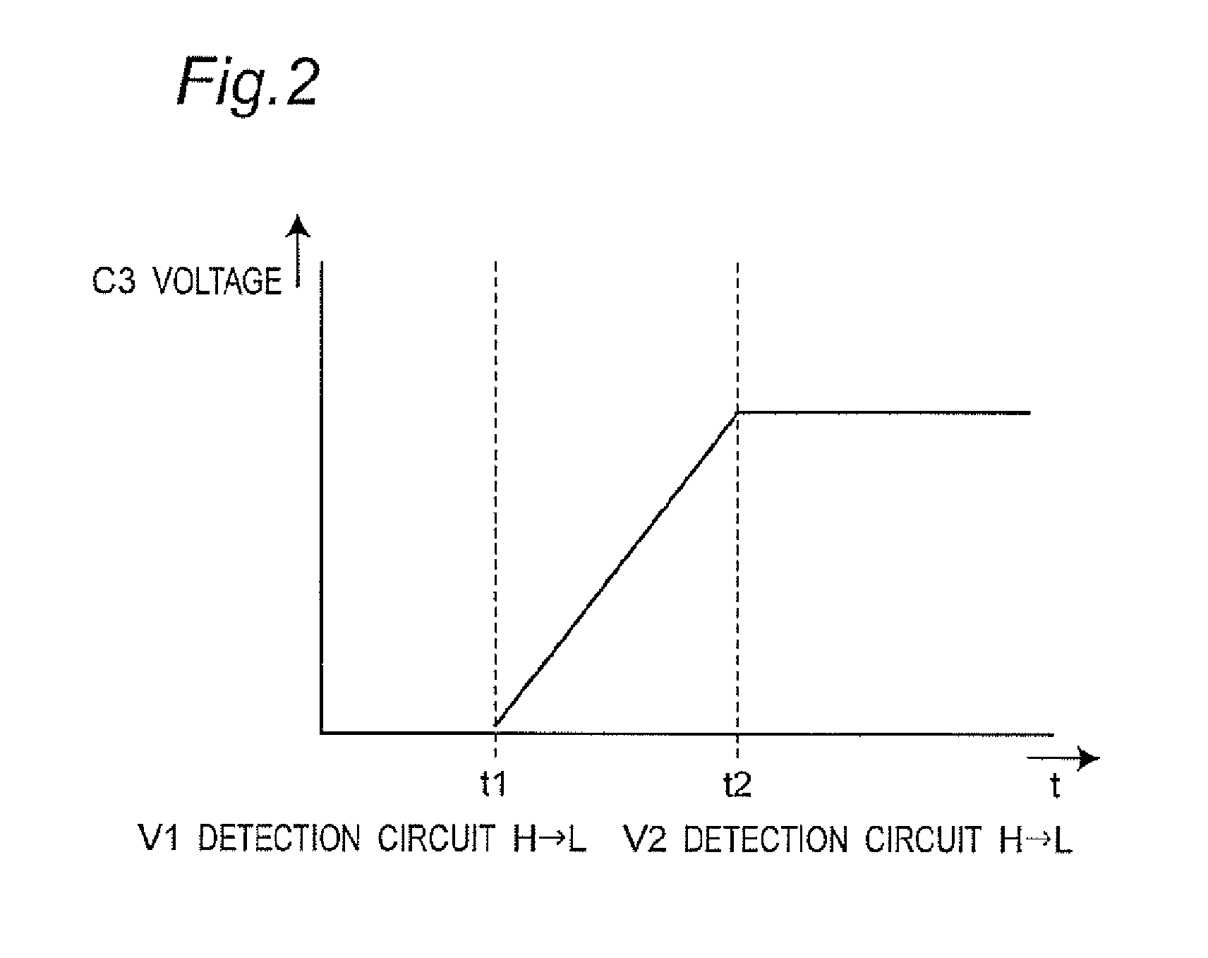
[0119]FIG. 12 shows a method for comparing other change rates of the lamp voltages shifting from V1 to V2 according to Embodiment 2 of the present invention. In Embodiment 1, the shifts of the lamp voltages from V1 to V2 were detected and the lapse of time t during the shifts were compared as the change rates to discriminate the lamp types. In present Embodiment 2, the other change rates aye compared using the detection of the lamp voltage shifting from V1 to V2 in the same manner.

[0120] Namely, since the expression: dV / dt=(V2−V1) / (t2−t1), described in Embodiment 1, can also be expressed as: (Vt−Vt−1) / {t−(t·1)}, when values, each obtained such that from a lamp voltage Vt at a timing t, a lamp voltage Vt−1 at a timing just before the timing t is subtracted and then divided by the time required: {t−(t·1)}, are added from V1 to V2, a value reflecting the inclination dV / dt from V1 to V2 can be calculated. Naturally, when this added value is divided by the time required (t2−t1) for the ...

embodiment 3

[0126]FIG. 13 shows a circuit diagram of a high-intensity discharge lamp lighting apparatus according to Embodiment 3. Compared with the lighting apparatus of FIG. 1, the following points are different. The step-down chopper circuit composed of the switching element Q2, diode D6, inductor L2, and capacitor C2 is omitted, and the function of the step-down chopper circuit is realized such that: the switching elements Q3 and Q4 are alternately switched on and off with a low frequency in stable lighting; the switching element Q6 is switched with a high frequency when the switching element Q3 is in on-state; and the switching element Q5 is switched with a high frequency when the switching element Q4 is in on state.

[0127] A further different point is that the igniter circuit IG in the lighting apparatus of FIG. 1 is omitted, and instead a start pulse generation circuit composed of an LC series resonant circuit of an inductor L3 and a capacitor C5 is added. The igniter circuit IG in FIG. ...


PUM


Abstract

There is provided a high-intensity discharge lamp lighting apparatus to be loaded with a plurality of types of high-intensity discharge lamps and connected with any one of the lamps to be lighted, and the apparatus comprises a power conversion circuit for converting power supplied from a DC power source to supply the power to a high-intensity discharge lamp and a lighting control circuit for controlling the supply power of the power conversion circuit, wherein the type of the connected high-pressure discharge lamp is determined based upon a change rate of an electric characteristic of the high-intensity discharge lamp during a specific period, and the connected high-intensity discharge lamp is lighted with a desired electric characteristic selected based upon the determination result, thereby enabling discrimination of types of rated power of the plurality of types of lamps by the same detection method and the same control method irrespective of states in starting of the lamps, and by enabling the discrimination before stable lighting of the lamp, it is possible to start the discharge lamp with little stress applied to the discharge lamp.

Description

TECHNICAL FIELD [0001] The present invention relates to a discharge lamp lighting apparatus fox electronically lighting a high-intensity discharge lamp, and to a luminaire and an illumination system which comprise the discharge lamp lighting apparatus. BACKGROUND ART [0002] Conventionally, a copper-iron type stabilizer has been mainstream as a high-intensity discharge lamp lighting apparatus for lighting a high-intensity discharge lamp (hereinafter, simply referred to as “discharge lamp” or “HID lamp”). However, an electronic ballast is recently becoming mainstream which uses a large number of electronic components with the aim of size and weight reduction as well as a function increase of a stabilizer. This electronic ballast is briefly described below. [0003] A direct-current (DC) power source circuit section including a rectification circuit is connected to an alternating-current (AC) power source. A power conversion circuit section capable of adjusting and controlling a supply p...

Claims


Application Information

Patent Timeline
IPC IPC(8): H05B41/24H05B41/288H05B41/292H05B41/36H05B41/38
CPCH05B41/288H05B41/2883H05B41/2885H05B41/36Y10S315/05Y02B20/204Y02B20/206Y10S315/07H05B41/384Y02B20/00
Inventor KUMAGAI, JUNNAGATA, SATORUMAEHARA, MINORUKOMATSU, NAOKI
Owner MATSUSHITA ELECTRIC WORKS LTD
Why Eureka
Try Eureka