
Power supply apparatus

a technology of power supply and power semiconductor, which is applied in the direction of motor/generator/converter stopper, dynamo-electric converter control, instruments, etc., can solve the problems of reducing the life of power semiconductor devices too much, and reducing the life of power semiconductor devices. , to achieve the effect of reducing the difference, preventing temperature rise, and maintaining the life of power semiconductor devices

Active Publication Date: 2007-09-13
SANSHA ELECTRIC MFG
View PDF1 Cites 11 Cited by
  • Summary
  • Abstract
  • Description
  • Claims
  • Application Information

AI Technical Summary

Benefits of technology

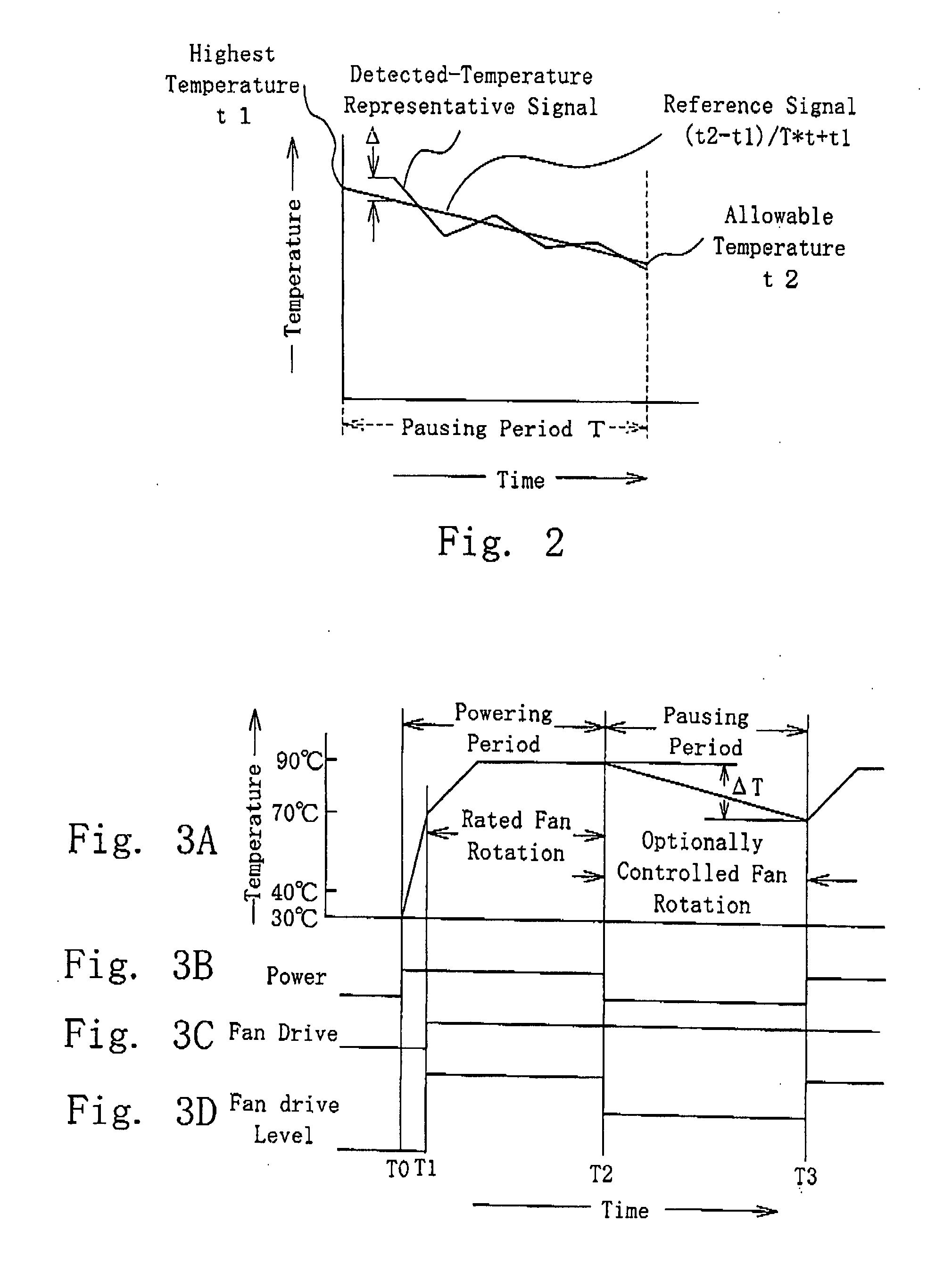
[0007]During the pausing period, the rotation rate of the fan of the power supply apparatus arranged as described above is controlled in such a manner that the temperature of the power semiconductor device at the beginning of the pausing period can decrease to the intended temperature at the end of the pausing period. Thus, at the end of the pausing period, the temperature of the power semiconductor device can be the intended temperature. The intended temperature can be property set so that the difference between the temperature of the power semiconductor device when it is operating and the temperature of the device when it is not operating, can be reduced, which can maintain the life of the power semiconductor device as long as possible.. In addition, since the fan is continuously rotating during the pausing period, heat does not stand, which can prevent components around the power semiconductor device from being thermally stressed.
[0009]The temperature represented by the measured-temperature representative signal may be the temperature giving thermal stress which components of the power supply apparatus disposed around the power semiconductor device can endure. The power semiconductor device may be mounted on a heat sink, and these power supply apparatus components may be disposed around the power semiconductor device. With this arrangement, it is possible not only to reduce the difference between the temperature of the power semiconductor device when it is operating and the temperature when it is not operating, to thereby maintain the long life of the power semiconductor device, but also to prevent the components around the power semiconductor device from being thermally stressed.

Problems solved by technology

Power semiconductor devices of such power supply apparatus are subjected to frequent temperature changes, which further reduces the lives of the semiconductor devices.
The following problem occurs when the fan is stopped at the same time as the power supply apparatus activation switch is turned off.
This, however, causes the temperature of the power semiconductor devices to be lowered too much, and, therefore, the life of the power semiconductor devices cannot be maintained.

Method used


Image

  • Power supply apparatus
  • Power supply apparatus
  • Power supply apparatus

Examples


Embodiment Construction

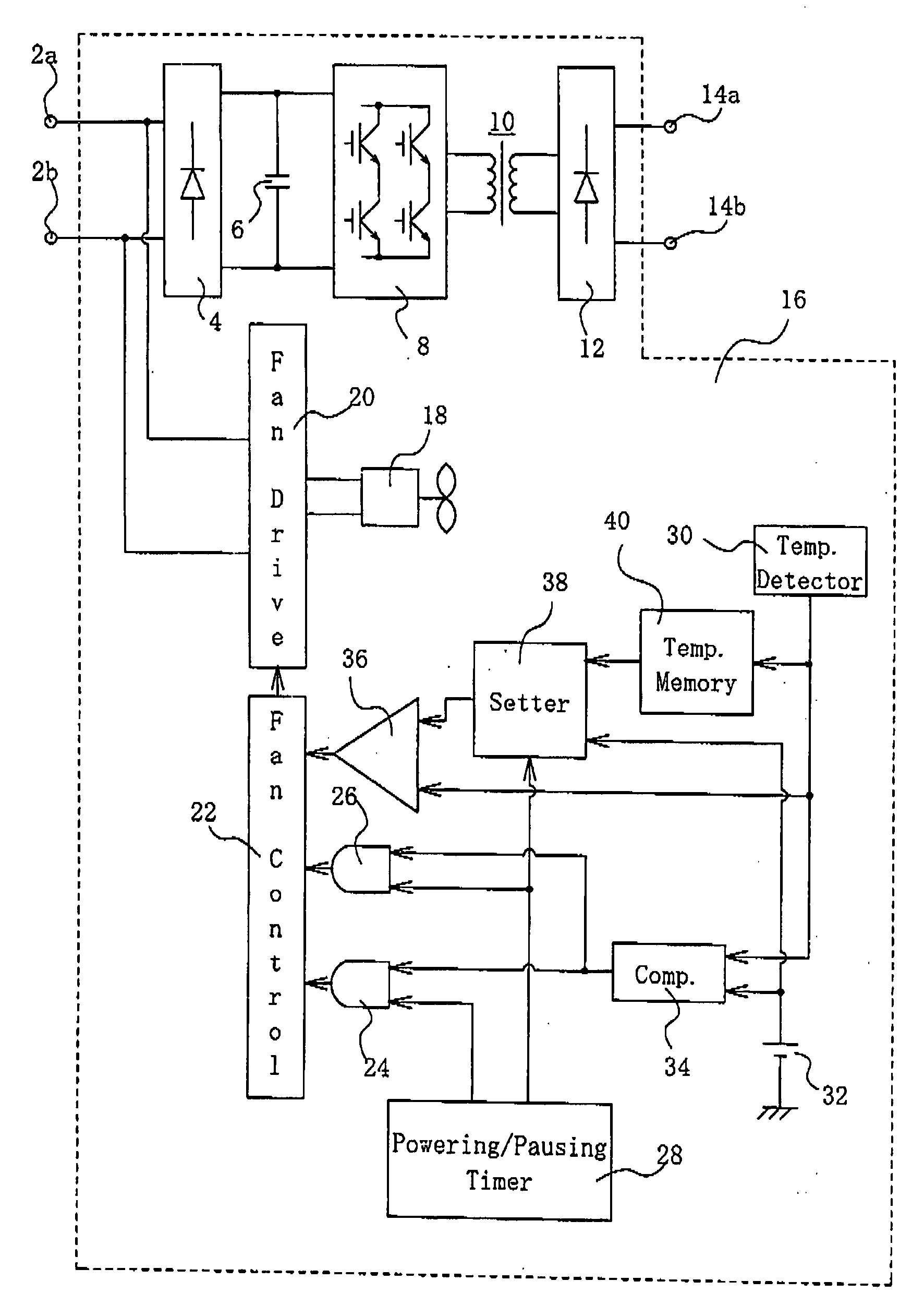
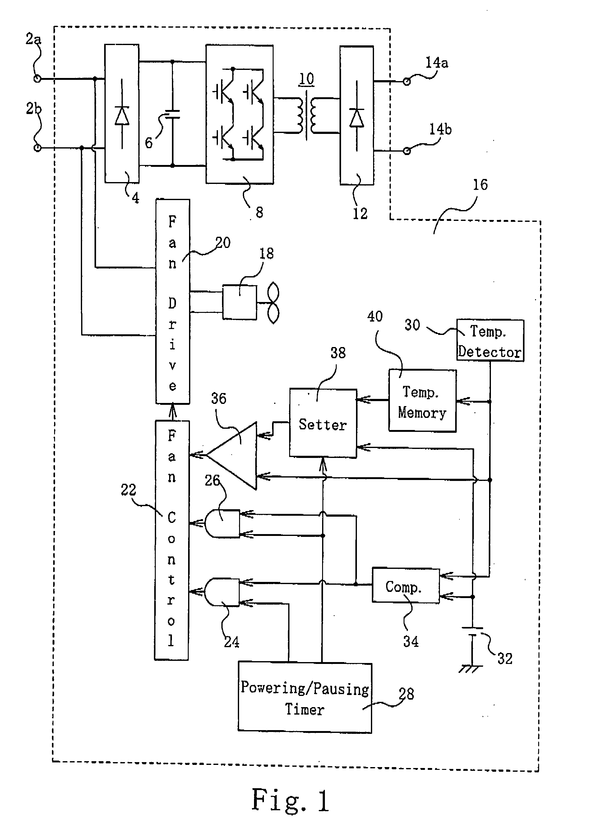
[0022]A power supply apparatus according to a first embodiment of the present invention may be used for an arc welder. As shown in FIG. 1, the power supply apparatus according to the first embodiment has power supply terminals 2a and 2b, through which a commercial AC voltage is supplied to the apparatus. The commercial AC voltage applied to the terminals 2a and 2b is coupled to rectifying means, e.g. an input-side rectifying circuit 4, for rectification. The rectifying circuit 4 includes a plurality of power semiconductor devices, e.g. rectifying diodes, forming a rectifying bridge circuit. The voltage resulting from the rectification is smoothed by smoothing means, e.g. a smoothing capacitor 6, connected in the output of the input-side rectifying circuit 4, into a DC voltage. The resultant DC voltage is converted to a high-frequency voltage by DC-to-high-frequency converting means, e.g. an inverter 8. The inverter 8 is configured as a bridge circuit which is formed by power semicon...


PUM


Abstract

A power supply unit includes an input-side rectifying circuit (4), an inverter (8) and an output-side rectifying circuit (12), which include power semiconductor devices. The power supply unit is powered during a powering period, and the powering is interrupted during a pausing period. The powering and pausing periods alternate. A fan (18) is driven during each powering period to cool the power semiconductor devices. A temperature detector (30) measures the temperature of the power semiconductor devices and develops a measured-temperature representative signal. A setter (38) produces a reference value, which decreases over the pausing period from the measured-temperature representative signal at the beginning of the pausing period to an intended-temperature representative signal representing the temperature to be attained by the power semiconductor devices at the end of the pausing period. The reference value is prepared from the measured-temperature representative signal at the beginning of the pausing period, the intended-temperature representative signal, and the length of the pausing period. An error amplifier (36) and a fan control unit (22) control the rotation rate of the fan (18) to make the measured-temperature representative signal track the reference value.

Description

[0001]This invention relates to a power supply apparatus, and, more particularly to a power supply apparatus having its heat generating components cooled by a fan.BACKGROUND OF THE INVENTION[0002]Power supply apparatuses employ power semiconductor devices, such as diodes, transistors and IGBTs. The life of power semiconductor devices tends to be shorter as the difference between the temperature of the devices when they are operating and the temperature when they are not operating becomes larger. When a power supply apparatus is used with, for example, an arc welder, a cutter, or an electroplating apparatus, it may be subjected to alternation between activation and deactivation at relatively short intervals. Power semiconductor devices of such power supply apparatus are subjected to frequent temperature changes, which further reduces the lives of the semiconductor devices. JP 2000-166217 A proposes a technique for solving this problem,[0003]According to JP 2000-166217A, when the powe...

Claims


Application Information

Patent Timeline
Patent Type & Authority Applications(United States)
IPC IPC(8): H02H7/08
CPCH05K7/20209H02M3/00
Inventor ISHII, HIDEOARAI, TORU
Owner SANSHA ELECTRIC MFG
Learn More