Synchronization timing detecting apparatus, receiving apparatus, and synchronization timing detecting method

a synchronization timing and detecting apparatus technology, applied in the direction of synchronisation signal speed/phase control, orthogonal multiplex, amplitude demodulation, etc., can solve the problem of increasing the circuit size of the receiving apparatus, increasing power consumption, and more likely to incorrectly detect the peak of the cross-correlation value that is generated, so as to reduce the sampling rate of the reception signal, suppress the increase in circuit size and power consumption, and maintain the effect of establishing synchronization accuracy

Inactive Publication Date: 2007-09-13
RENESAS ELECTRONICS CORP
View PDF1 Cites 46 Cited by
  • Summary
  • Abstract
  • Description
  • Claims
  • Application Information

AI Technical Summary

Benefits of technology

[0023]By such method, it is possible to detect a synchronization timing, which is a correlation peak position, from the first correlation value calculated using the sampling point and the second correlation value (interpolation correlation value) that interpolates a plurality of the first correlation values even if a sampling rate of the input signal is low. This enables to reduce a sampling rate of a reception signal while maintaining an accuracy in establishi

Problems solved by technology

Furthermore, if a detection threshold for a correlation peak in the threshold evaluator 414 is set smaller in order to detect a small correlation peak, it is more likely to incorrectly detect a peak in a cross-correlat

Method used


Image

  • Synchronization timing detecting apparatus, receiving apparatus, and synchronization timing detecting method
  • Synchronization timing detecting apparatus, receiving apparatus, and synchronization timing detecting method
  • Synchronization timing detecting apparatus, receiving apparatus, and synchronization timing detecting method

Examples


first embodiment

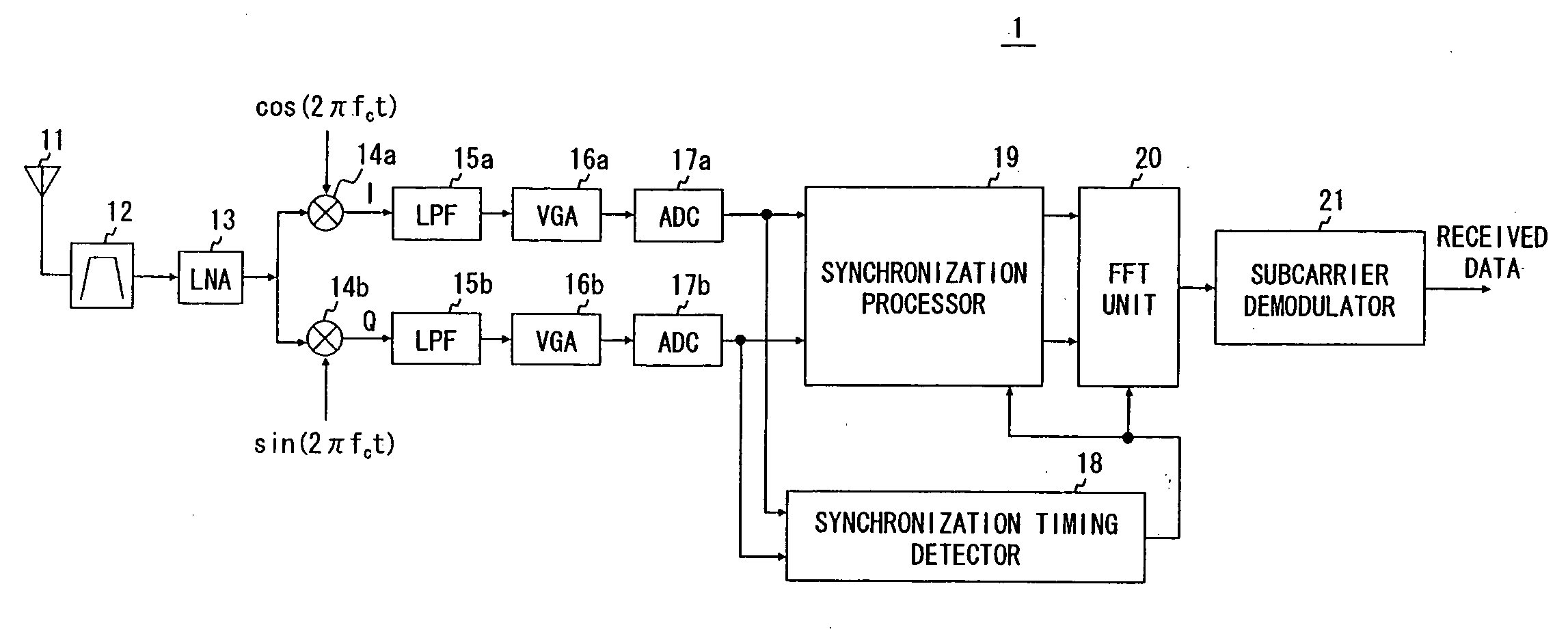
[0034]A configuration of a MB-OFDM receiving apparatus 1 according to this embodiment is shown in FIG. 1. Firstly an outline of receiving operations by the MB-OFDM receiving apparatus 1 is described hereinafter in detail. A signal received by an antenna 12 is selected of a frequency band by a band pass filter (BPF) 12. After that the signal is amplified by a low noise amplifier (LNA) 13. The BPF 12 is a filter for selecting a band group to receive from a plurality of band groups of the MB-OFDM. The signal amplified by the LNA 13 is input to mixers 14a and 14b and quadrature demodulated. Note that a frequency hopping is performed in the MB-OFDM. Accordingly a local frequency fc generated by an oscillator not shown and input to the mixers 14a and 14b are periodically switched according to a frequency hopping pattern.

[0035]An In-phase component (I component) signal I(t) and a Quadrature component (Q component) signal Q(t) of a complex baseband signal that are demodulated by the mixers ...

second embodiment

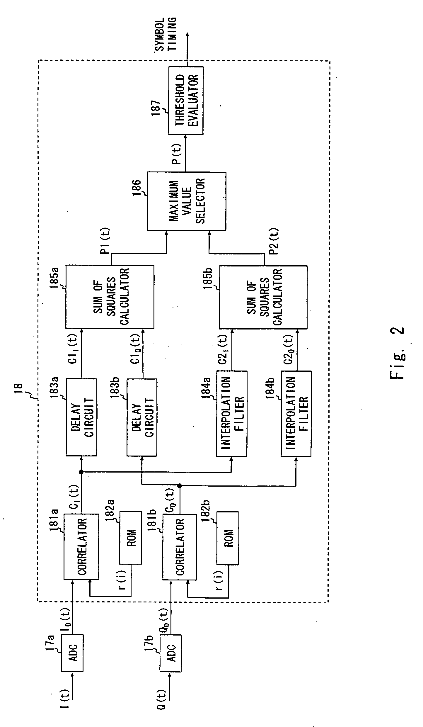
[0054]The synchronization timing detector 18 according to a first embodiment of the present invention is described with a case when interpolating a middle point between two consecutive sampling points. However the number of interpolation points between the two consecutive sampling points may be two or more. At this time, the interpolation filters 184a and 184b may calculate cross-correlation values C2I(k,t) and C2Q(k,t) for a given point t(k

C2I(k,t)=∑i=-qq+1CI(k+i)sinc(t-i)(6)C2Q(k,t)=∑i=-qq+1CQ(k+i)sinc(t-i)(7)

[0055]Further, the maximum value selector 186 may be configured in a way that it selects the maximum value from a sum of squares of a cross-correlation value in the number of N interpolation points and a sum of squares of a cross-correlation value in the sampling points, where the number of the interpolation points between the sampling points is N.

[0056]By ...


PUM


Abstract

A synchronization timing detecting apparatus includes a correlation calculator configured to generate a first correlation value by calculating a cross-correlation between an input signal being sampled and a reference signal or an auto-correlation of the sampled input signal, an interpolation processor configured to generate a second correlation value interpolating a plurality of the first correlation values having a different combination of sampling points of the input signal, and a detector to detect a synchronization timing based on the first and the second correlation values.

Description

BACKGROUND OF THE INVENTION[0001]1. Field of the Invention[0002]The present invention relates to a receiving apparatus for controlling a phase of a reception signal using a synchronization signal included in the reception signal.[0003]2. Description of Related Art[0004]To send and receive framed or packetized data between a sending and a receiving apparatuses, a correlation method is used to establish a frame synchronization of a reception signal in the receiving apparatus (see Japanese Unexamined Patent Application Publication No.2005-176184). In the correlation method, when the sending apparatus sends an information signal to the receiving apparatus, a reference signal is added to the beginning of the information signal. The reference signal is a signal sequence having a specified signal pattern repeated periodically. Such reference signal is hereinafter referred to as a preamble. The receiving apparatus calculates a cross-correlation value between a signal pattern of a known prea...

Claims


Application Information

Patent Timeline
IPC IPC(8): H04L27/06H04L7/00H04B1/709H04B1/713H04J11/00H04L27/38
CPCH04L7/0058H04L27/2675H04L27/2662H04L7/042
Inventor INAGAWA, OSAMUTSUCHIDA, JUNYA
Owner RENESAS ELECTRONICS CORP
Why Eureka
Try Eureka