Endoscope system

a technology of endoscope and endoscope, which is applied in the field of endoscope systems, can solve the problems of unable unable to integrate dichroic mirrors, and difficult to perform high-resolution observation, etc., and achieve the effect of high-resolution images

Inactive Publication Date: 2007-09-13
OLYMPUS CORP
View PDF24 Cites 39 Cited by
  • Summary
  • Abstract
  • Description
  • Claims
  • Application Information

AI Technical Summary

Benefits of technology

[0012] The present invention has been conceived in light of the circumstances described above, and an object thereof is to provide an endoscope which has a reduced-diameter insertion portion, which is capable of observation using a plurality of types of light with different spectral characteristics, and which can obtain high-resolution images.

Problems solved by technology

However, since it is difficult to integrate the dichroic mirrors in the tip of an insertion portion of the endoscope, the dichroic mirrors are provided as external units.
However, in the case of the Publication of Japanese Patent No. 3683271, there is a drawback in that the resolution of the image acquired by the image-acquisition means depends on the number of optical fibers constituting the fiber bundle for transmitting this image.
In other words, because the number of optical fibers that can be disposed inside the thin insertion portion of the endoscope is limited, when the diameter of the insertion portion is reduced, there is a problem in that it is difficult to perform high-resolution observation.
Furthermore, in the endoscope in Japanese Unexamined Patent Application, Publication No. 2001-190489, more space is required for disposing the plurality of image-acquisition optical systems; therefore, there is a problem in that it is difficult to reduce the diameter of the tip of the insertion portion of the endoscope.
Therefore, there is a problem in that it is not possible to perform high-resolution observation in this endoscope.

Method used


Image

  • Endoscope system
  • Endoscope system
  • Endoscope system

Examples


first embodiment

[0052] An endoscope system 1 according to the present invention will be describe below with reference to FIGS. 1 to 4.

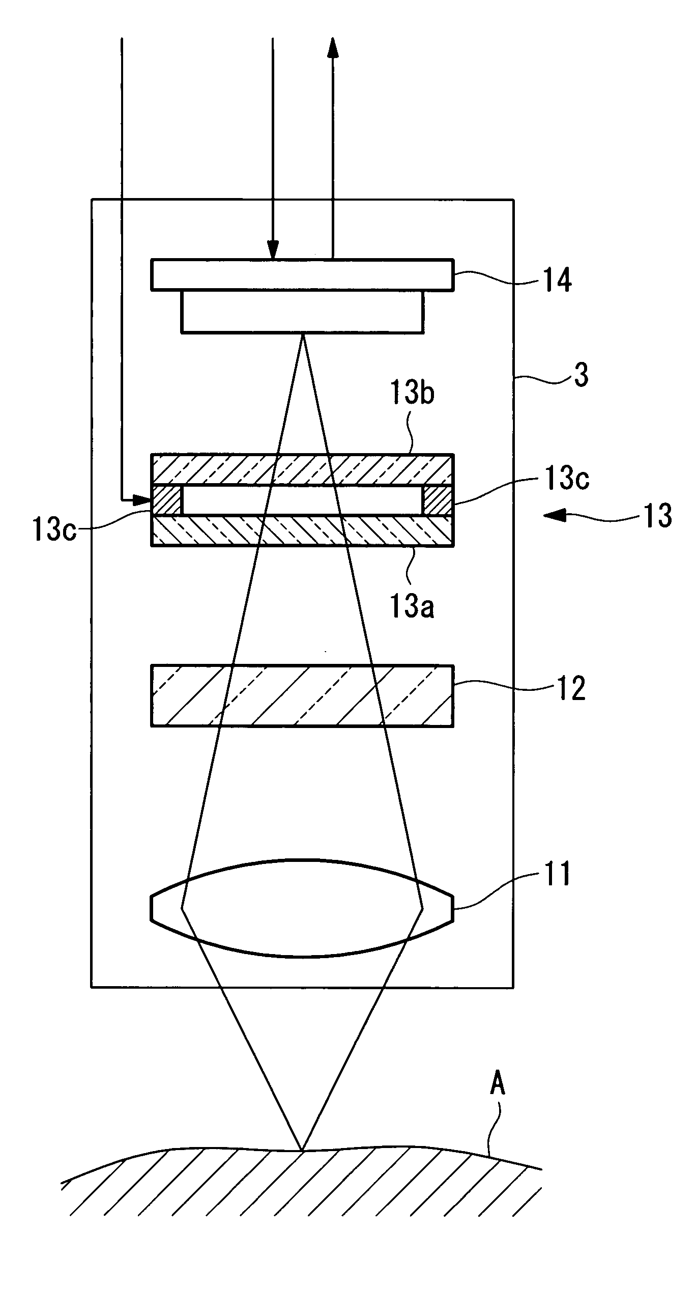
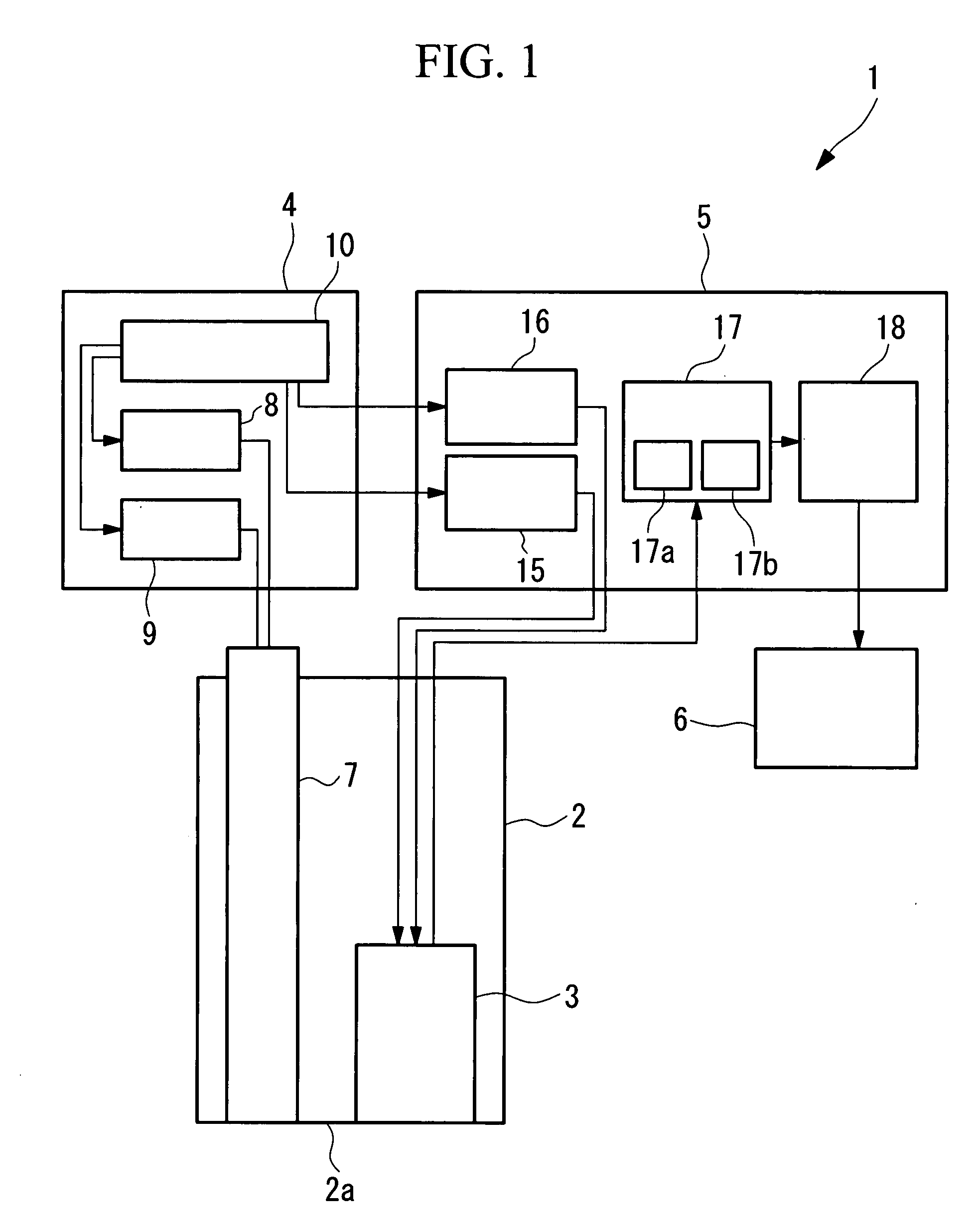
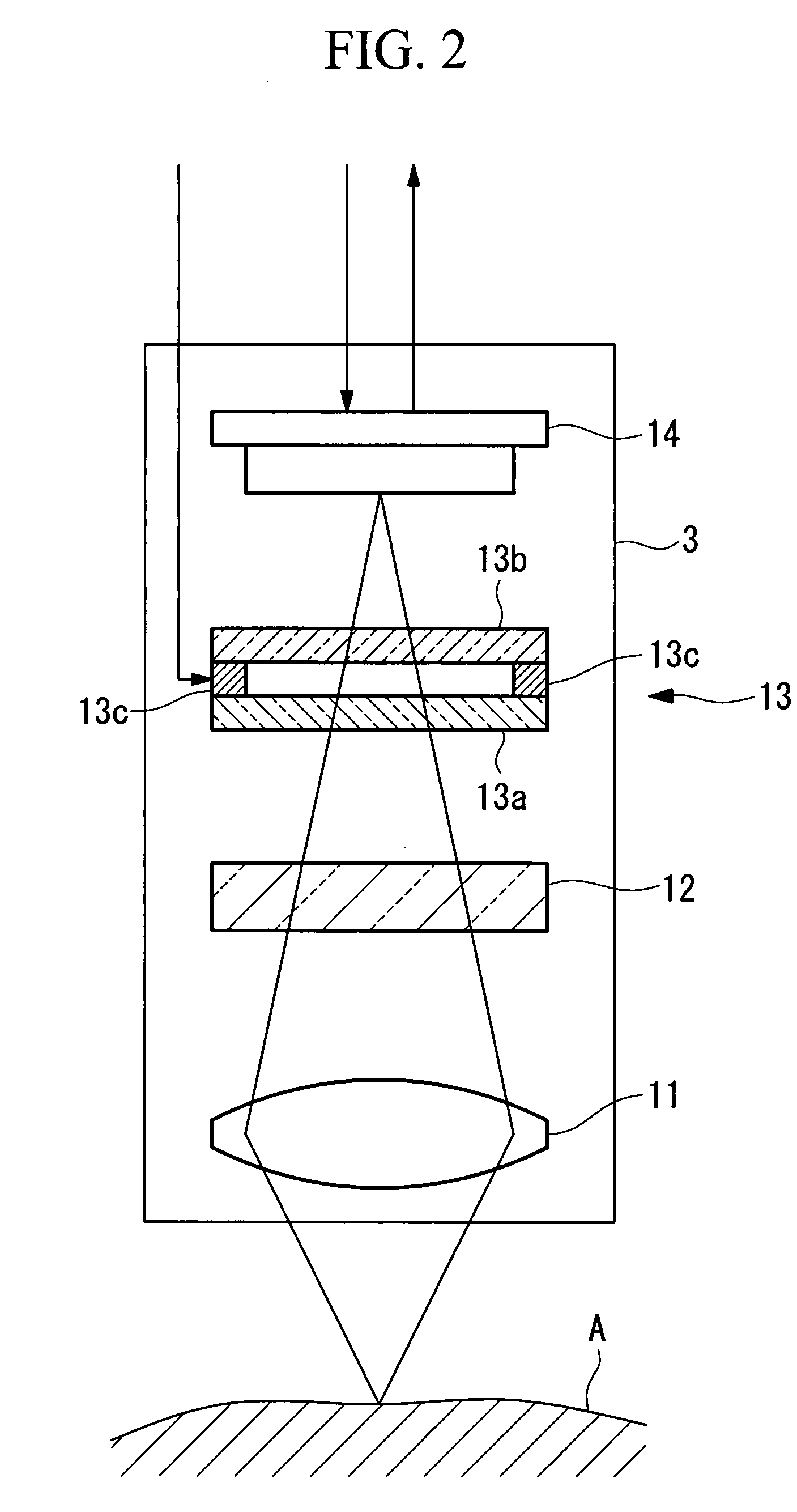
[0053] As shown in FIG. 1, the endoscope system 1 according to this embodiment includes an insertion portion 2 for insertion into a body cavity of a living organism, an image-acquisition unit (image-acquisition portion) 3 disposed inside the insertion portion 2, a light-source unit (light-source portion) 4 for emitting a plurality of types of light, a control unit (control portion) 5 for controlling the image-acquisition unit 3 and the light-source unit 4, and a display unit (output portion) 6 for displaying images acquired by the image-acquisition unit 3.

[0054] The insertion portion 2 has extremely narrow outer dimensions, allowing it to be inserted inside the body cavity of the living organism. The insertion portion 2 includes the image-acquisition unit 3 and a light guide (light-guiding optical system) 7 for transmitting light from the light-source unit 4 to a ti...

second embodiment

[0097] Next, an endoscope system according to the present invention will be described below with reference to FIG. 6.

[0098] In the description of this embodiment, parts having the same configuration as those in the endoscope system 1 according to the first embodiment described above are assigned the same reference numerals, and a description thereof shall be omitted here.

[0099] As shown in FIG. 6, in the endoscope system according to this embodiment, the wavelength of the excitation light emitted from the excitation light source 9 differs from that in the endoscope system 1 according to the first embodiment. Based on this, in the endoscope system according to this embodiment, the transmittance characteristics of the variable-spectrum device 13 and the excitation-light-cutting filter 12 differ from those in the endoscope system 1 according to the first embodiment.

[0100] In the endoscope system according to this embodiment, a semiconductor laser having a peak wavelength of 405±5 nm ...

third embodiment

[0115] Next, an endoscope system 1′ according to the present invention will be described with reference to FIGS. 7 and 8.

[0116] In the description of this embodiment, parts having the same configuration as those in the endoscope system 1 according to the first embodiment described above are assigned the same reference numerals, and a description thereof is omitted here.

[0117] The endoscope system 1′ according to this embodiment differs from the endoscope system 1 according to the first embodiment in the configuration of a light-source unit 4′ and the transmittance characteristics of the variable-spectrum device 13 and the excitation-light-cutting filter 12.

[0118] As shown in FIG. 7, the light-source unit 4′ of the endoscope system 1′ according to this embodiment includes two excitation light sources 21 and 22.

[0119] The first excitation light source 21 is a semiconductor laser emitting first excitation light with a peak wavelength of 660±5 nm. It is possible to excite a fluoresce...


PUM


Abstract

The invention provides an endoscope which has a reduced-diameter insertion portion, which is capable of observation using a plurality of types of light with different spectral characteristics, and which can obtain high-resolution images. The invention provides an endoscope system comprising a light-source portion for emitting a plurality of types of irradiation light having different spectral characteristics, which are radiated towards an acquisition object; an optical system for transmitting the irradiation light towards the acquisition object; an image-acquisition portion, disposed in a portion inserted inside the body cavity and capable of acquiring fluorescence emitted from the acquisition object due to irradiation with the plurality of types of irradiation light, and light of a different wavelength band from the fluorescence; a variable-spectrum unit, disposed in a light path between the image-acquisition portion and a tip of the portion inserted inside the body cavity and capable of changing a wavelength band of light incident on the image-acquisition portion from the acquisition object by varying spectral characteristics thereof; and a control portion for controlling the light-source portion, the variable-spectrum unit, and the image-acquisition portion in association with the spectral characteristics of the irradiation light that the light-source portion emits, the spectral characteristics of the variable-spectrum unit, and a light exposure level of the image-acquisition portion.

Description

BACKGROUND OF THE INVENTION [0001] 1. Field of the Invention [0002] The present invention relates to endoscope systems. [0003] This application is based on Japanese Patent Application No. 2006-051914, the content of which is incorporated herein by reference. [0004] 2. Description of Related Art [0005] In endoscopy of living organisms using endoscope systems, in order to observe the condition of the living organism with good resolution, it is preferable to carry out endoscopy using a plurality of types of light having different spectral characteristics. [0006] Examples of endoscopes capable of carrying out observation using a plurality of types of light having different spectral characteristics are disclosed in the Publication of Japanese Patent No. 3683271 and Japanese Unexamined Patent Application, Publication No. 2001-190489. [0007] In the endoscope disclosed in the Publication of Japanese Patent No. 3683271, in order to acquire a plurality of types of images using the plurality o...

Claims


Application Information

Patent Timeline
Patent Type & Authority Applications(United States)
IPC IPC(8): A61B1/06A61B6/00
CPCA61B1/043A61B5/0071A61B1/0638A61B1/00186A61B5/0084
Inventor NAKAOKA, MASAYA
Owner OLYMPUS CORP
Why Eureka
Try Eureka