
Implantable medical lead

a technology of medical leads and leads, applied in the direction of spinal electrodes, internal electrodes, therapy, etc., can solve the problems of unsteerable percutaneous leads and subsequent explantation difficulties, and achieve the effects of improving the flexibility of the tip of the lead, facilitating post-implant anchoring, and improving the steerability

Inactive Publication Date: 2007-09-13
BOSTON SCI NEUROMODULATION CORP
View PDF9 Cites 108 Cited by
  • Summary
  • Abstract
  • Description
  • Claims
  • Application Information

AI Technical Summary

Benefits of technology

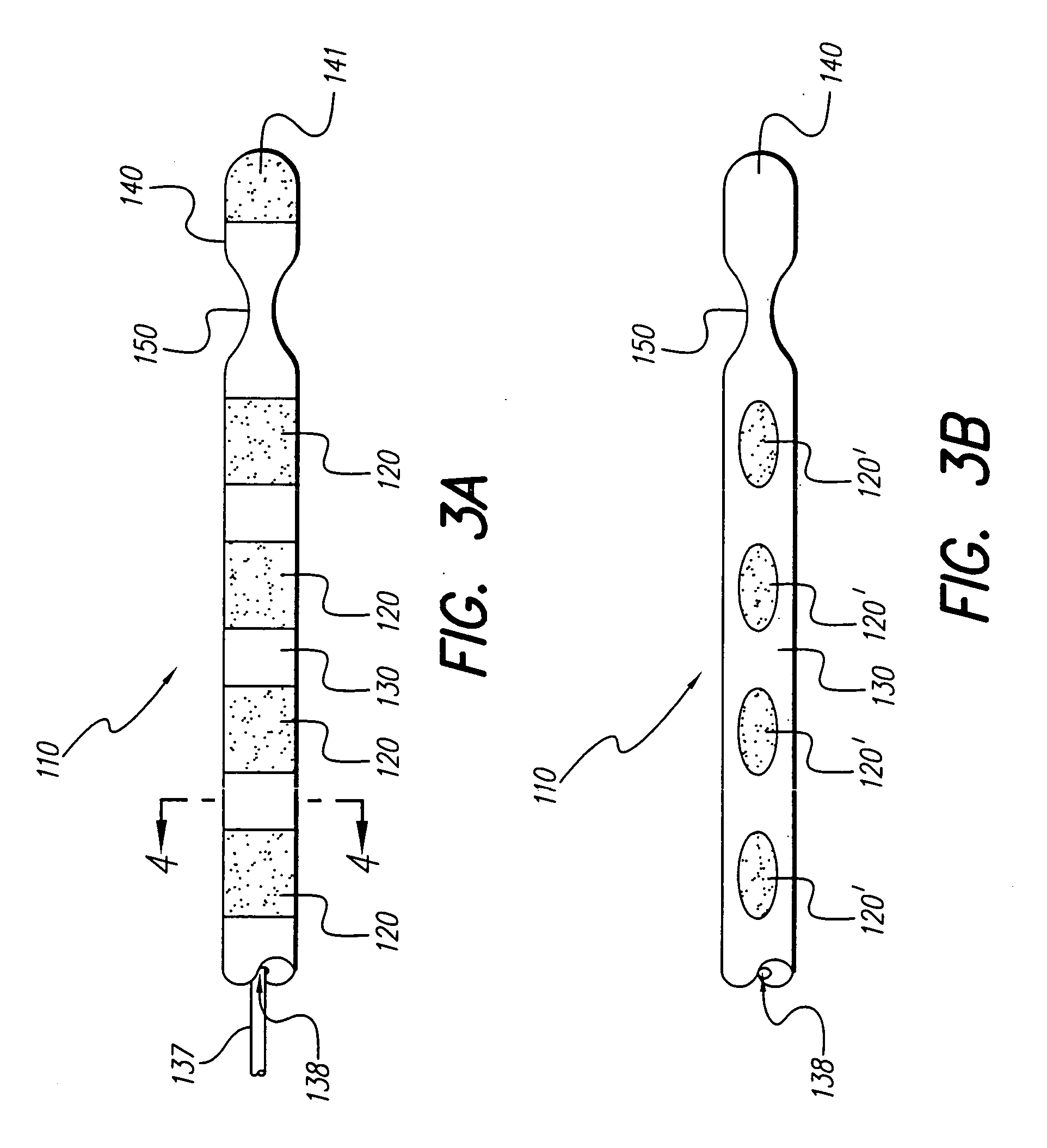
[0014] In one aspect of the invention, there is provided a percutaneous lead which is substantially isodiametric, except for a concave, circumferential neck located on the distal portion of the lead. The circumferential concavity is smooth and free of sharp edges, particularly at the surface of the lead, which edges can cause the lead to get caught on the discharge end of a cannula during insertion or withdrawal from the cannula. The isodiametric profile of the lead allows the lead to be easily inserted through an introduction cannula and also through tough body tissue. The concavity also advantageously provides a deflection point so that the lead distal tip can bend when a bent stylet is inserted into the lumen of the lead. Additionally, the concave neck of the lead can help to anchor the lead by facilitating the ingrowth of adhesion or scar tissue into and around the concave neck. While anchoring does occur, nevertheless, during explantation, the lead may be pulled from tissue without application of excessive force. The lead design avoids the use of passive protruding structures such as tines or fins which can help fixate the lead long-term but which protruding structures would also render the percutaneous lead unsteerable and make subsequent explantation difficult.
[0016] It is another feature of the invention to provide a lead with a concave neck having no sharp edges, which concave neck improves the lead's tip flexibility and improves steerablity and, moreover, facilitates post-implant anchoring.
[0017] It is yet another feature of the invention to provide a lead having a tip that is not initially bent, but that is capable of being aggressively angled during use, without requiring that the stylet already be aggressively pre-bent or angled.

Problems solved by technology

The lead design avoids the use of passive protruding structures such as tines or fins which can help fixate the lead long-term but which protruding structures would also render the percutaneous lead unsteerable and make subsequent explantation difficult.

Method used


Image

  • Implantable medical lead
  • Implantable medical lead
  • Implantable medical lead

Examples


Embodiment Construction

[0026] The following description is of the best mode presently contemplated for carrying out the invention. This description is not to be taken in a limiting sense, but is made merely for the purpose of describing the general principles of the invention. The scope of the invention should be determined with reference to the claims.

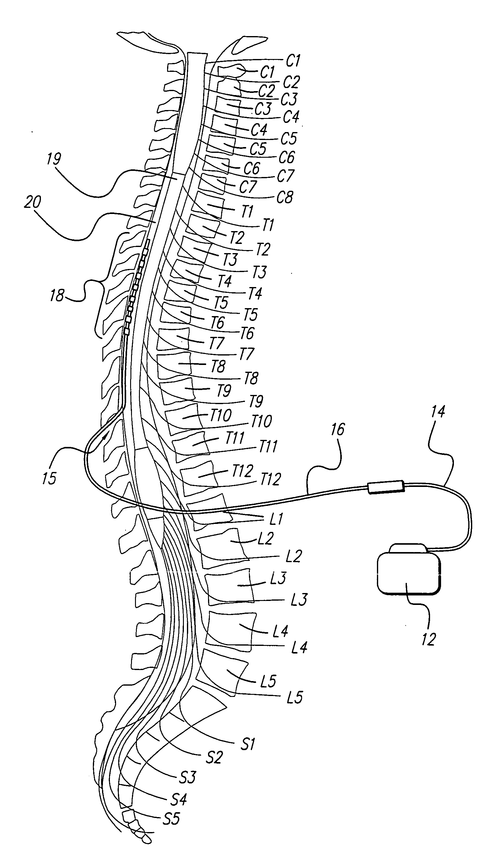
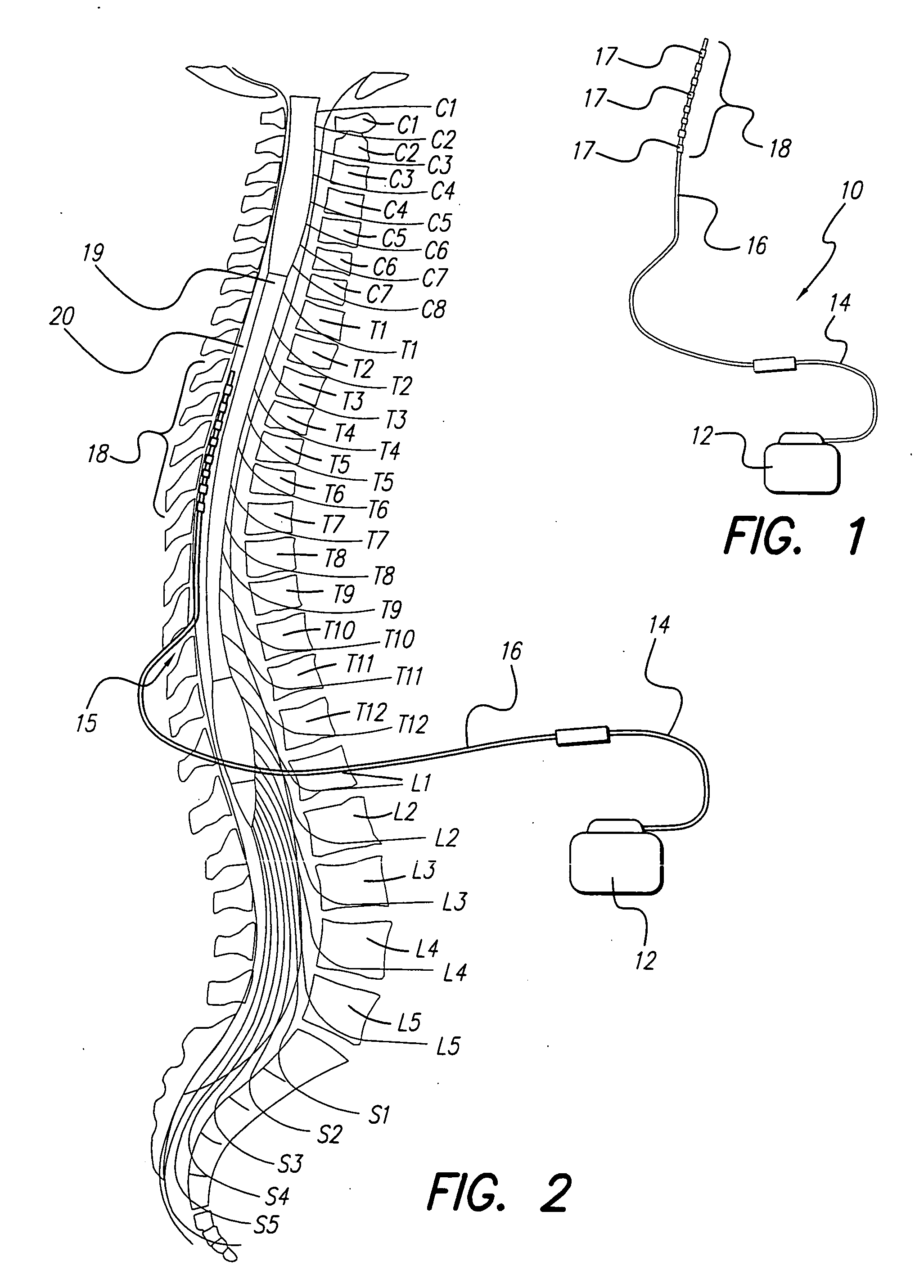
[0027]FIG. 1 shows a generalized stimulation system that may be used in spinal cord stimulation (SCS), as well as other stimulation application. Such a system typically comprises an implantable pulse generator (“IPG”) 12, an optional lead extension14, an electrode lead 16 and an electrode array 18. The electrode array includes a plurality of electrode contacts 17 (also referred to herein as “electrodes”). In a percutaneous lead, the electrodes 17 can be arranged in an in-line electrode array 18 near the distal end of the lead 16. Other electrode array configurations can also be used. The IPG 12 generates stimulation current pulses that are applied to selec...


PUM


Abstract

An improved percutaneous lead is provided. The lead has a circumferential, concave neck located on the distal portion of the lead and a stylet lumen traversing through the lead including through the concave neck. The concave neck has a narrower circumference than the remainder of the lead. The concave neck is designed to bend up to 45 degrees with a pre-curved stylet inserted into the stylet lumen. The presence of a concave neck permits the ingrowth of tissue into and around the concave neck, thereby helping to anchor the lead post-implant. The concavity in the neck presents no sharp edges to disrupt the isodiametric lead profile.

Description

[0001] The present application claims the benefit of U.S. Provisional Patent Application Ser. No. 60 / 469,081, filed 08 May 2003, which application is herein incorporated by reference in its entirety.BACKGROUND OF THE INVENTION [0002] The present invention relates to implantable medical leads used to provide electrical stimulation and, more particularly, to steerable, percutaneous leads. [0003] Over the past few decades, significant advances have been made in treating intractable, chronic pain. One method of treating such pain uses an implanted electrode array to stimulate a target area of the spinal cord to alleviate pain. Stimulation of this target area results in paresthesia which can replace the sensation of pain with an alternate, tingling sensation. While the mechanism of pain relief resulting from such electrical stimulation is not well understood, one theory, known as the “Meizack-Wall Gate-Control Theory,” hypothesizes that stimulating specific spinal cord nerves inhibits th...

Claims


Application Information

Patent Timeline
Patent Type & Authority Applications(United States)
IPC IPC(8): A61N1/05
CPCA61N1/0558
Inventor BRADLEY, KERRYLAURO, B. RENO
Owner BOSTON SCI NEUROMODULATION CORP
Learn More