Wheel and other bearing hubs safety restraint devices, locks and visual warning indicators

a technology of safety restraint devices and bearing hubs, which is applied in the direction of instruments, machines/engines, heat measurement, etc., can solve the problems of lack of lubrication, unexpected separation, and integrity of locks, and achieve the effects of preventing harm or injury, reducing friction, and reducing friction

Inactive Publication Date: 2007-09-20
MELBERG NELS +1
View PDF14 Cites 23 Cited by
  • Summary
  • Abstract
  • Description
  • Claims
  • Application Information

AI Technical Summary

Benefits of technology

[0027]It is a further object of the invention to provide an early warning jam nut system for securing wheel bearing hub assemblies in place that will also provide a measure of protection against wheel bearing hub assembly separation from a spindle of a non-driven or driven axle by providing a jam nuts constructed of high strength steel that have both a greater mass and larger diameter such that they will block and temporarily retain wheel hubs in place even if complete bearing failure should occur, for at least a sufficient period of time that a vehicle or equipment operator will be able to take action to control the vehicle to prevent any harm or injury.
[0028]It is another object of the invention to provide a jam nut system for wheel bearing hubs mounted on axle spindles wherein the jam nuts can be easily tightened using conventional ratchet tools and r

Problems solved by technology

A particular problem associated with substantially any type of vehicle that has wheels mounted on bearings, including commercial and non commercial vehicles is a sudden and unexpected separation of one or more wheel assemblies from a non driven axle spindle or driven axle drive tube spindle to which they are mounted.
Such separations are brought about by bearing failures, hub failures and bearing hub assembly retaining failures.
Such failures may be caused by many problems including bearing assembly wear, lack of lubrication and loosening of jam or lock nuts used to secure the bearing assemblies in safe operative condition.
When a failure of an outer bearing assembly occurs, the bearings can destroy the integrity of the lock and jam nuts such that it is possible that the wheel hub can thereby become separated from the axle spindle or drive tube spindle.
The separation of a wheel bearing hub from a vehicle traveling at any speed creates a potentially catastrophic situation.
Considering that an average two wheel bearing hub includes two rims, two tires and a brake drum that can have a combined weight of 400 or more pounds, if a wheel bearing hub of a truck separates at a speed of 55 mph or greater, not only is there probable loss of vehicle control that can result in possible injury or death, but the wheel assembly itself can become a damaging or lethal projectile as it careens into oncoming or other vehicular traffic or into pedestrians.
Such possible tragedies are caused not only by the inherent conventional wheel bearing hub designs, and/or mounting techniques, which are in conventional use, but also due to poor or improper maintenance.
Currently, it is virtually impossible for a driver or federal or state Department of Transportation inspector to inspect wheel bearings and locking mechanisms unless the wheel bearing hub cover is removed or the drive axle is removed.
As a practical matter, many wheel, or other machinery,

Method used


Image

  • Wheel and other bearing hubs safety restraint devices, locks and visual warning indicators
  • Wheel and other bearing hubs safety restraint devices, locks and visual warning indicators
  • Wheel and other bearing hubs safety restraint devices, locks and visual warning indicators

Examples


first embodiment

[0049]With continued reference to the drawings, FIG. 3 is a cross section illustrating a wheel bearing early warning jam nut and indication warning system in accordance with the invention. A wheel bearing hub assembly 40 includes an early warning jam nut 42 adapted to be tightened on a threaded outer end portion 13 of a spindle 11 of a non driven vehicle axle 12 so as to provide a locking force relative to an inner factory nut 30 in order to retain the factory nut 30 in place and prevent loosening of the nut. In preferred embodiments, the early warning jam nut 42 will be made more massive, of a greater diameter and of a heavier grade / higher strength steel than the inner factory nut 30. A lock washer may be seated between the jam nut 42 and nut 30.

[0050]As shown in FIG. 3, the diameter of early warning jam nut 42 is shown as being larger than that of the factory nut 30, and is also as large or slightly larger than the diameter “D” of an outer bearing bore 43 of the wheel bearing hub....

second embodiment

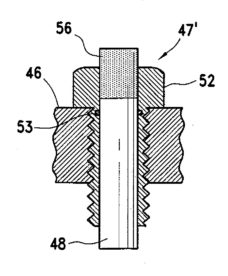
[0071]The operation of the warning and indicating device of this embodiment is the same as the Should a relative change occur in the rotational positions of the wheel bearing hub and the bearings, the indicator 48 / 48′ will be forced outwardly of the wheel bearing hub to give the visual indication of a problem. Also, when the warning device also includes a temperature sensor 55, should the temperature within the wheel bearing hub bearing cavity elevate above a predetermined level, the temperature indicator will extend outwardly of the wheel bearing hub to give a visual warning.

[0072]Devices in accordance with of the present invention may be produced and / or installed by power unit drive axle manufacturers, vehicle assembly manufacturers, dealers and / or end users. Various embodiments may be shipped as a single unit, others may be shipped as sub-assemblies and used in the vehicle and other machinery production processes.

[0073]The visual indicators and / or early warning jam nuts in accor...


PUM


Abstract

Wheel and other bearing restraint jam nuts and early warning visual warning indicators for use with bearing hubs including driven and non-driven wheel bearing hubs wherein each jam nut is adapted to be received on either a threaded drive axle tube spindle or an axle spindle by use of a convention tool and such that the jam nut is of a size to obstruct wheel bearing hub separation in the event of a bearing failure and wherein a portion of the jam nut is engageable to force an indicator outwardly of the wheel bearing hub whenever the wheel bearing hub is not properly rotating about it's axis of rotation to thereby provide a visual indication of a potential problem with the bearings or other components within the wheel or other bearing hub.

Description

CROSS REFERENCE TO RELATED APPLICATIONS[0001]This application is a non-provisional application claiming the benefit of U.S. provisional application Ser. No. 60 / 784,191, filed Mar. 20, 2006, in the name of Nels Melberg, entitled, Hub Lock Visual Indicator and Safety Restraint System and Apparatus, the entire contents of which are incorporated herein by reference.BACKGROUND OF THE INVENTION[0002]1. Field of the Invention[0003]The present invention is generally directed to the field bearing hubs and support bearings for supporting rotating machinery or members and, in preferred embodiments to wheel bearing hubs and axle assemblies used on vehicles including all types of automobiles, trucks, trailers, aircraft, farm equipment and the like. The teachings of the invention also are applicable to other environments such as industrial machinery and the like. More particularly, the invention is directed to visual emergency warning indicators which reflect when bearings have become loose or th...

Claims


Application Information

Patent Timeline
IPC IPC(8): G01K1/02
CPCG01K13/08G01K5/62F16C19/364F16C19/525F16C19/548F16C2326/02
Inventor MELBERG, NELSEKMAN, JOHN M.
Owner MELBERG NELS
Why Eureka
Try Eureka