Tire Manufacturing Method, Preset Bead Molding Apparatus, and Preset Bead Molding

a tire and bead molding technology, applied in the field of tire manufacturing methods, can solve the problems of time-consuming, degrading the cycle time of the whole system, and affecting so as to reduce the intermediate stocks, prevent the uniformity of the product tires from being decreased, and form stably and accurately

Inactive Publication Date: 2007-09-20
BRIDGESTONE CORP
View PDF14 Cites 25 Cited by
  • Summary
  • Abstract
  • Description
  • Claims
  • Application Information

AI Technical Summary

Benefits of technology

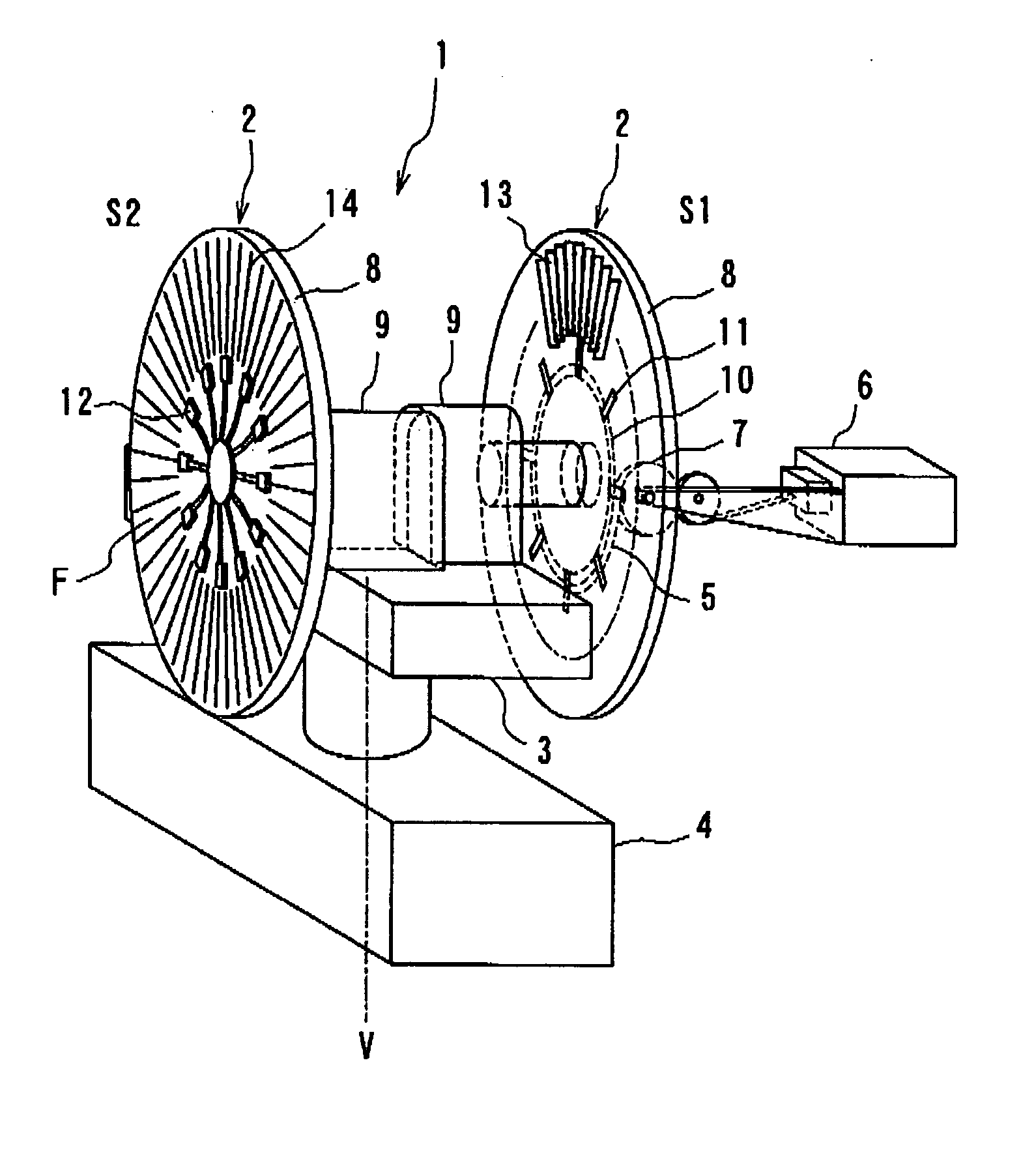
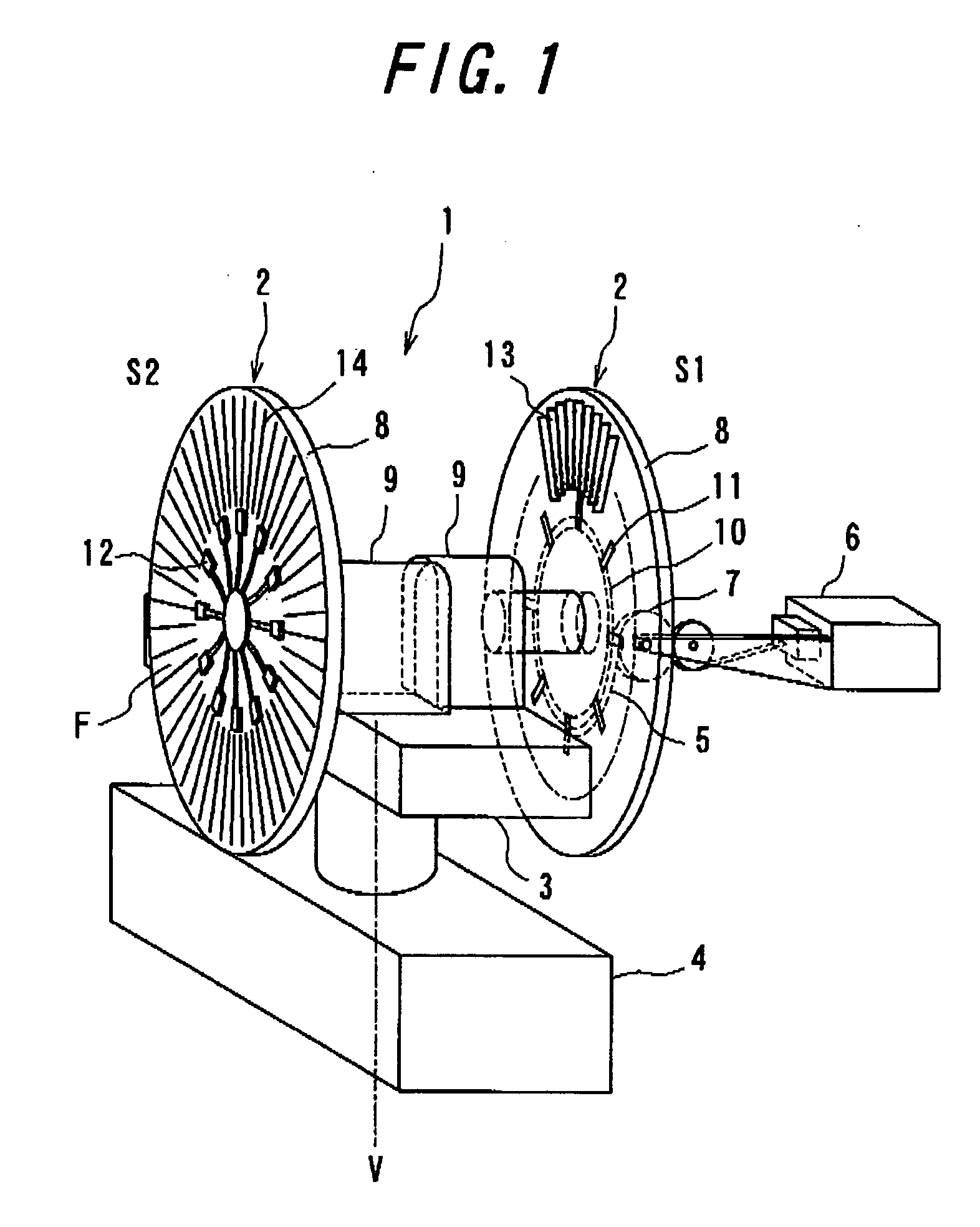
[0015] According to the tire manufacturing method of the first aspect, because the bead filler is formed with the ribbon-winding process, the nozzle of the extruder does not need to be replaced for a respective size of the bead filler unlike the method in which a rubber having a cross sectional shape substantially identical to that of the bead filler is wound for only one lap and thus the preset beads having various sizes can be manufactured in a mixed flow process. Therefore, it is possible to reduce the intermediate stocks of the preset beads and to suppress the gathering of the joint portion of the bead filler in the circumferential direction to prevent the uniformity of the product tires from being decreased. Moreover, according to the tire manufacturing method of the second aspect, the preset beads can be formed stably and accurately by laminating the ribbon-shaped bead filler rubber on a disk in parallel with the disk.
[0016] According to the tire manufacturing method of the third aspect, the tire manufacturing method of the first or second aspect can be realized and the above-mentioned effect can be achieved.
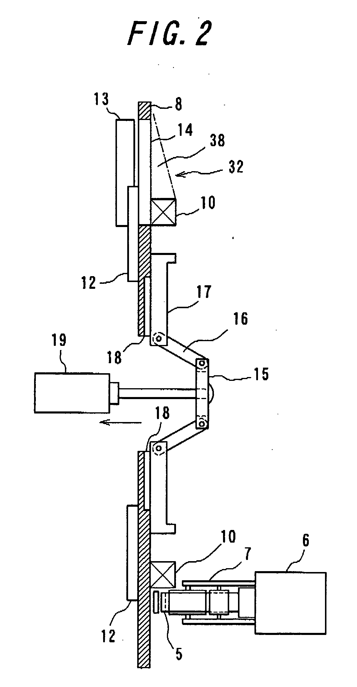
[0017] According to the tire manufacturing method of the forth aspect, because the bead core-holding device is configured as described above, the side face of the bead core is attracted and held on the disk by the magnets and thereafter a force is applied to the inner circumferential face of the bead core by the centering device to center the bead core. Therefore, it is possible to hold and center the bead cores in various sizes without replacing the centering device.
[0018] According to the tire manufacturing method of the fifth aspect, by arranging the preset bead-forming apparatus, a bead core-preparing station, a bead-handling robot and a preset bead storage station, transferring of the bead core as well as forming and transferring of the bead core are efficiently and quickly conducted. Therefore, it is possible to save labor and improve the productivity.
[0019] According to the tire manufacturing method of the sixth aspect, preset beads in different sizes may be manufactured in a mixed production system. Therefore, it is possible to produce in a large item small lot production.
[0020] According to the tire manufacturing method of the seventh aspect, the formed preset beads are inspected and then only non-defective products are supplied to the tire-building apparatus. Therefore, it is possible to supply the preset beads may be supplied to tire-building apparatus with a stable quality.

Problems solved by technology

Therefore, there is a problem that the process in the station needs much time and the cycle time of the whole system is degraded, so it has been practically demanded in actual use.
The replacement, however, is time consuming, so that considerable numbers of the bead fillers with a respective tire size need to be extruded in one time to maintain the operation rate of the extruder.
Thus, it results in unnecessary intermediate stocks of the preset beads, which wastes the space and the management of the intermediate stocks.
Second, in the method in which the bead filler rubber is wound for only one lap, joint portions gathers at one point in the circumference direction.
Such a joint portion may cause unevenness in the circumference direction of the preset bead, which may reduce the tire uniformity.
It is sometimes difficult to make such a extension evenly in the circumferential direction, which is also the cause to reduce the tire uniformity.

Method used


Image

  • Tire Manufacturing Method, Preset Bead Molding Apparatus, and Preset Bead Molding
  • Tire Manufacturing Method, Preset Bead Molding Apparatus, and Preset Bead Molding
  • Tire Manufacturing Method, Preset Bead Molding Apparatus, and Preset Bead Molding

Examples


examples

[0036] In order to evaluate an effect on the improvement of the uniformity of a product tire using the preset bead core according to the tire manufacturing method of the present invention, ten tires were experimentally manufactured for each of Example, which was provided with the preset beads manufactured according to the tire manufacturing method of the present invention, and Conventional Example, which was provided with preset beads formed by winding a rubber with a cross sectional shape generally identical to that of the bead filler in the green tire for only one lap. The uniformities of them were measured and compared. As a result, it is shown that the RFV (radial force variation) of the Example tires are smaller than those of the Conventional Example tires by 5N in average. It, therefore, is appreciated that the uniformity of the tire is improved.


PUM

PropertyMeasurementUnit
thicknessaaaaaaaaaa
widthaaaaaaaaaa
thicknessaaaaaaaaaa

Abstract

There is provided a method of tire manufacturing a tire in which preset-beads each preformed by mounting a bead filler on a bead core are disposed radially outward of a carcass band and both side portions of the carcass band are turned around the preset beads to build the tire. The method eliminates a need to bold the considerable intermediate stocks and does not deteriorate the tire uniformity due to the unevenness of the preset bead in the circumference direction. There are also provided an apparatus of forming a preset bead used therefore and a system of forming a preset bead. In the method of manufacturing a tire in which preset-beads each preformed by mounting a bead filler on a bead core are disposed radially outward of a carcass band and both side portions of the carcass band are turned around the preset beads to build the tire, the preset bead is formed by winding and laminating a ribbon-shaped filler rubber 5 radially outward of the bead core 10 over several laps.

Description

TECHNICAL FIELD [0001] The present invention relates to a method of manufacturing a tire in which preset beads each preformed by mounting a bead filler on a bead core are disposed radially outward of a carcass band and both side portions of the carcass band are turned around the preset beads to build the tire. RELATED ART [0002] Such a tire manufacturing method has been employed that preset-beads each preformed by mounting a bead filler on a bead core are disposed radially outward of a carcass band and both side portions of the carcass band are turned around the preset beads to build the tire (see Patent Document 1, for example). This method has an advantage that can save more space around a building drum and more time necessary for the assembly as compared with the method in which the bead core and the bead filler are separately assembled on a building drum. In this method, particularly when it is used with a so-called drum-flow building system which transfers a building drum from ...

Claims


Application Information

Patent Timeline
Patent Type & Authority Applications(United States)
IPC IPC(8): B29D30/00B29D30/48
CPCB29D30/0016B29D2030/482B29D2030/0044B29D30/48
Inventor SATA, YOSHIYUKI
Owner BRIDGESTONE CORP
Why Eureka
Try Eureka