Heat exchanger

a technology of heat exchanger and suction tube, which is applied in the direction of indirect heat exchanger, refrigeration components, lighting and heating apparatus, etc., can solve the problems of high cost of copper used to form suction tubes, and achieve the effect of reducing the hardness of said steel and facilitating tube bending

Inactive Publication Date: 2007-09-20
BUNDY REFRIGERATION INT HLDG BV
View PDF54 Cites 23 Cited by
  • Summary
  • Abstract
  • Description
  • Claims
  • Application Information

AI Technical Summary

Benefits of technology

[0004] According to a first aspect of the present invention, there is provided, a heat exchanger for connection to an evaporator of a heat transfer system using a working fluid that undergoes compression and evaporation, said heat exchanger comprising a first tube having a first end configured to be connected to an outlet of an evaporator to allow fluid transmission from said outlet; and a second tube having a first end configured to be connected to an inlet of the evaporator to allow fluid transmission t

Problems solved by technology

A problem with such an arrangement is the high c

Method used


Image

  • Heat exchanger
  • Heat exchanger
  • Heat exchanger

Examples


Embodiment Construction

FIG. 1

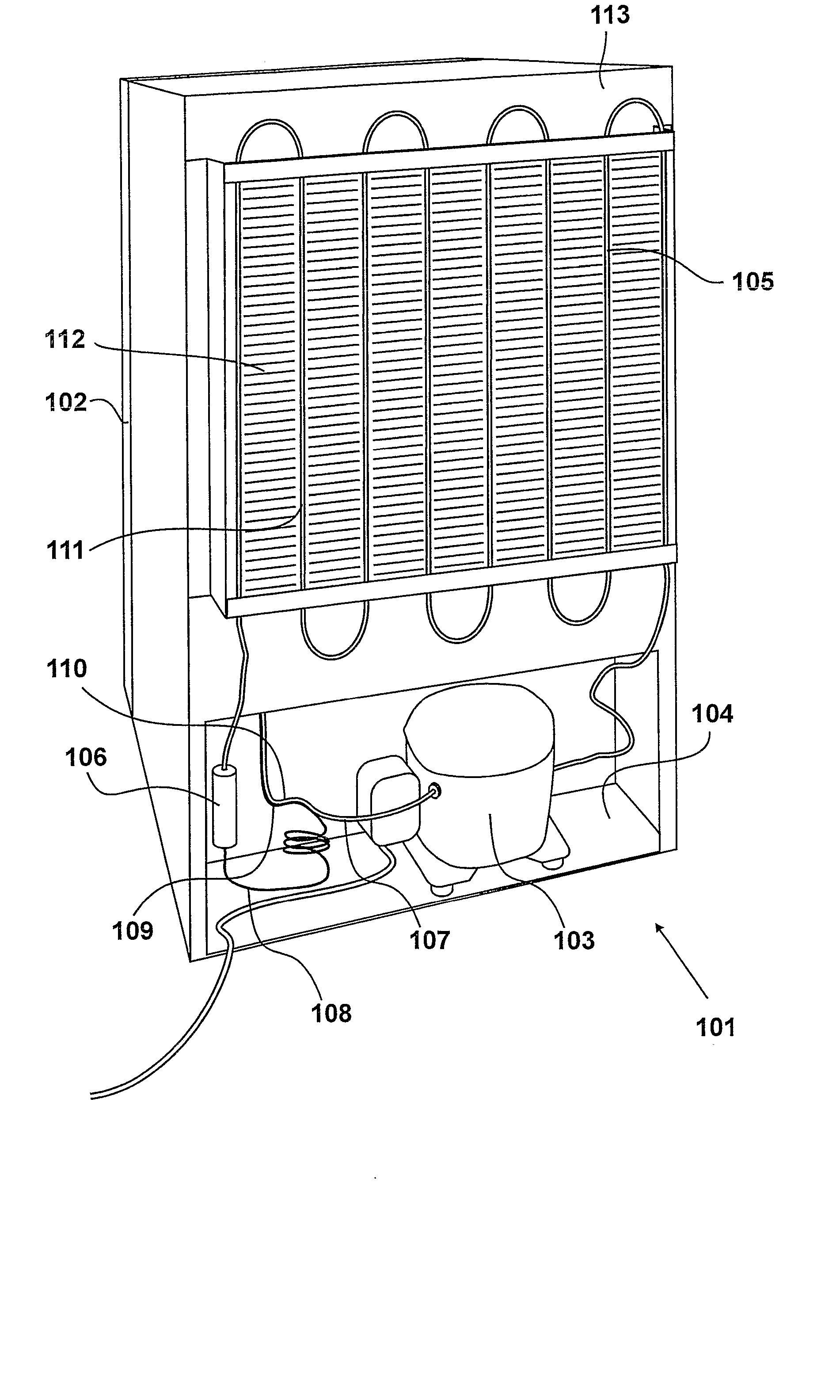
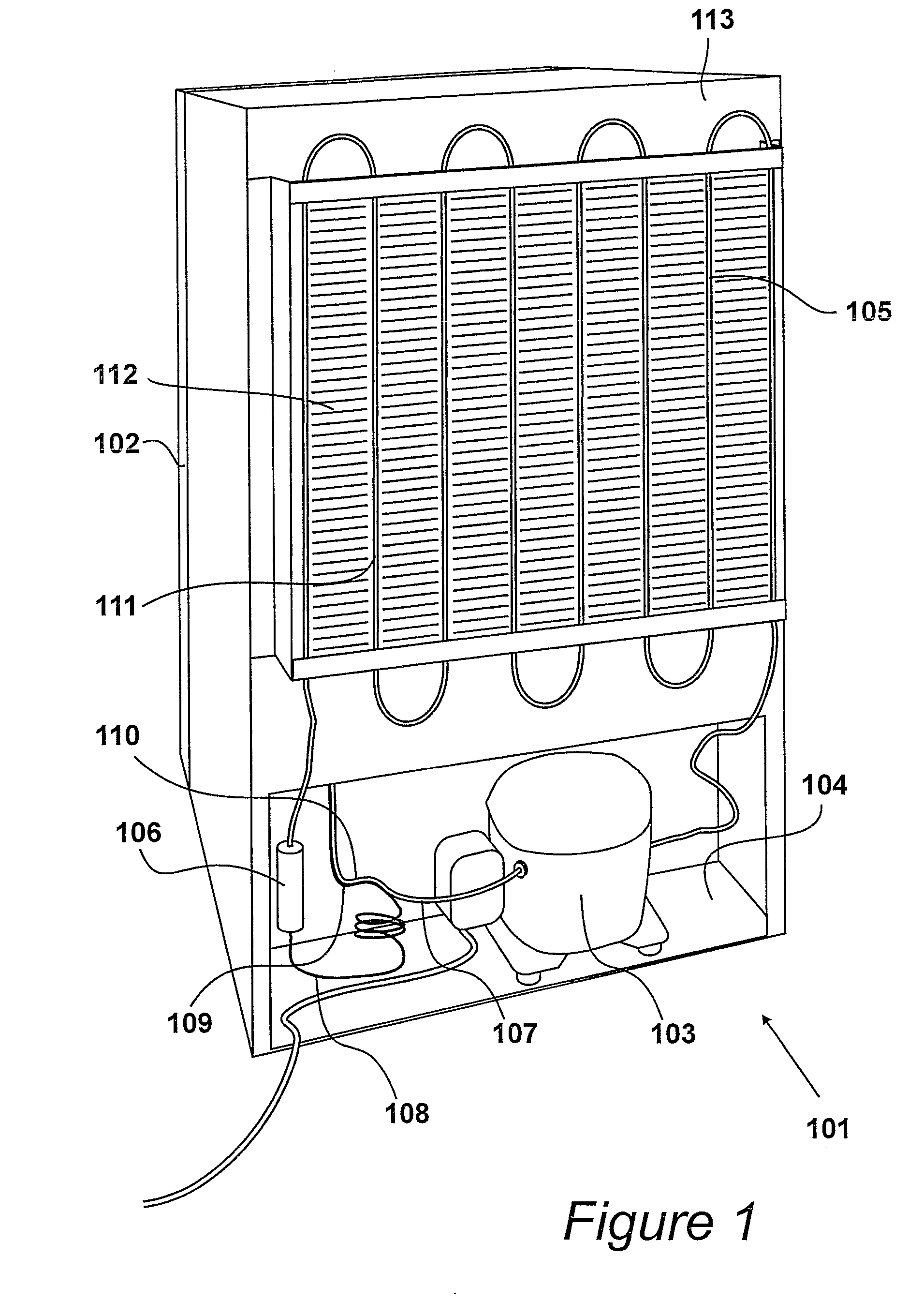
[0017] A rear perspective view of a domestic refrigeration unit 101 is shown in FIG. 1. In the present example, the refrigeration unit is a refrigerator having a door 102 at its front to allow access to a refrigeration cavity. The cavity is configured to provide cold storage for perishable goods such as food, drinks, etc.

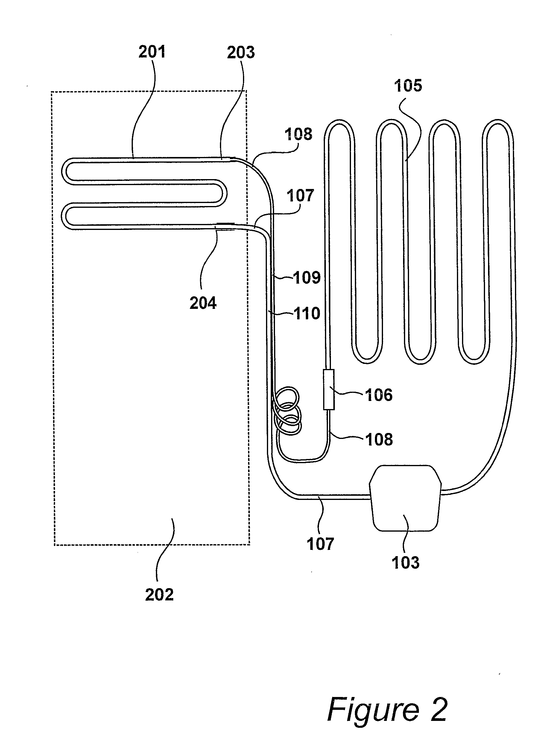
[0018] The refrigerator 101 has a heat transfer system which pumps heat from the refrigeration cavity to the air surrounding the refrigerator. The heat transfer system comprises an electrically powered compressor 103 located within a lower rear compartment 104 of the refrigerator, a condenser 105 mounted on a rear outer wall 113 of the refrigerator, a drying and filtering unit 106, and an evaporator (shown as 201 in FIG. 2) mounted within the refrigeration cavity.

[0019] The condenser 105 comprises a meandering tube 111 attached to a louvered panel 112 which assists transportation of heat from the tube 111 to the surrounding air during operation.

[0020] In ad...


PUM

PropertyMeasurementUnit
Fractionaaaaaaaaaa
Fractionaaaaaaaaaa
Fractionaaaaaaaaaa

Abstract

A heat exchanger ( 301, 501, 601 ) comprising a first tube ( 107, 507, 607 ) for fluid transmission and a second tube ( 108, 508, 608 ) for fluid transmission within a heat transfer system that uses a working fluid which undergoes compression and evaporation. The first tube is placed in thermal contact with the second tube for a portion ( 109,110 ) of the respective lengths of the first tube and the second tube so as to allow an exchange of heat between the fluid within said tubes. The first tube ( 107, 507, 607 ) is constructed from steel alloy which has alloyed components to reduce the hardness of the steel to facilitate tube bending within a heat transfer system, thereby allowing the first tube to be constructed from the steel within the heat transfer system, in preference to copper.

Description

BACKGROUND OF THE INVENTION [0001] The present invention relates to heat exchanger for connection to an evaporator of a heat transfer system, a heat transfer system including a heat exchanger connected to an evaporator, a method of manufacturing a heat exchanger, and a tube for use in a heat transfer system. [0002] In domestic refrigerators and freezers, it is usual to have a capillary tube which transmits liquid refrigerant to an evaporator, and a copper suction tube which transmits gaseous refrigerant from the evaporator. It is also known to arrange a portion of the length of the capillary tube and suction tube together to form a heat exchanger. Consequently, refrigerant fluid transmitted from the evaporator is warmed by the fluid transmitted to the evaporator, and similarly fluid transmitted to the evaporator is cooled by the fluid returned from the evaporator. [0003] A problem with such an arrangement is the high cost of the copper used to form the suction tube. BRIEF SUMMARY OF...

Claims


Application Information

Patent Timeline
IPC IPC(8): F28F1/00F25B40/06F25B41/06F28D7/00F28D7/10F28F21/08
CPCF25B40/06F25B41/067F25B2400/052F25B2400/054Y10T29/49359F28D7/10F28F19/06F28F21/082F28D7/0016
Inventor VIKLUND, BENGT AKEBERGGREN, GOTE GUNNARMOGENSEN, LEO OSTERGAARD
Owner BUNDY REFRIGERATION INT HLDG BV
Why Eureka
Try Eureka