Piezoelectric substance element, liquid discharge head utilizing the same and optical element

a liquid discharge head and piezoelectric technology, applied in the direction of device material selection, inking apparatus, generator/motor, etc., can solve the problems of not describing satisfactory characteristics in the pzt , the desired piezoelectric characteristics may not be obtained. , to achieve the effect of satisfactory characteristics, good elasticity and good elasticity

Active Publication Date: 2007-09-20
CANON KK
View PDF16 Cites 25 Cited by
  • Summary
  • Abstract
  • Description
  • Claims
  • Application Information

AI Technical Summary

Benefits of technology

[0009] An object of the present invention is to provide a film of a ferroelectric substance or a piezoelectric substance, having satisfactory characteristics and showing little deterioration in the characteristics even when the film thickness fluctuates. Another object of the present invention is to provide a piezoelectric substance element, having

Problems solved by technology

Also because of this inversion in the crystal phases, desired satisfactory characteristics may not be obtained in case of forming a thin film.
Also the latter film is a film of tetragonal only wit

Method used


Image

  • Piezoelectric substance element, liquid discharge head utilizing the same and optical element
  • Piezoelectric substance element, liquid discharge head utilizing the same and optical element
  • Piezoelectric substance element, liquid discharge head utilizing the same and optical element

Examples


example 1

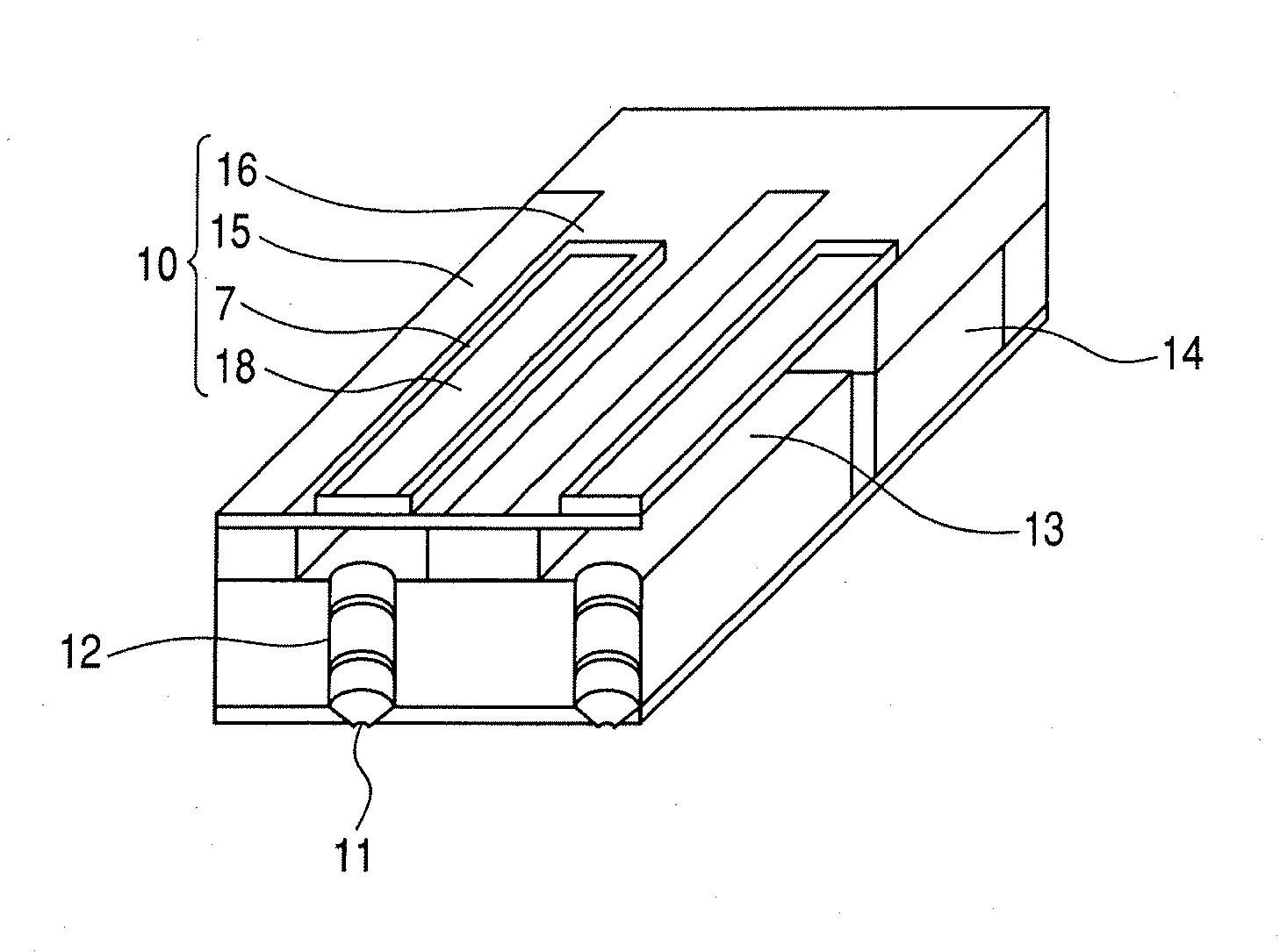
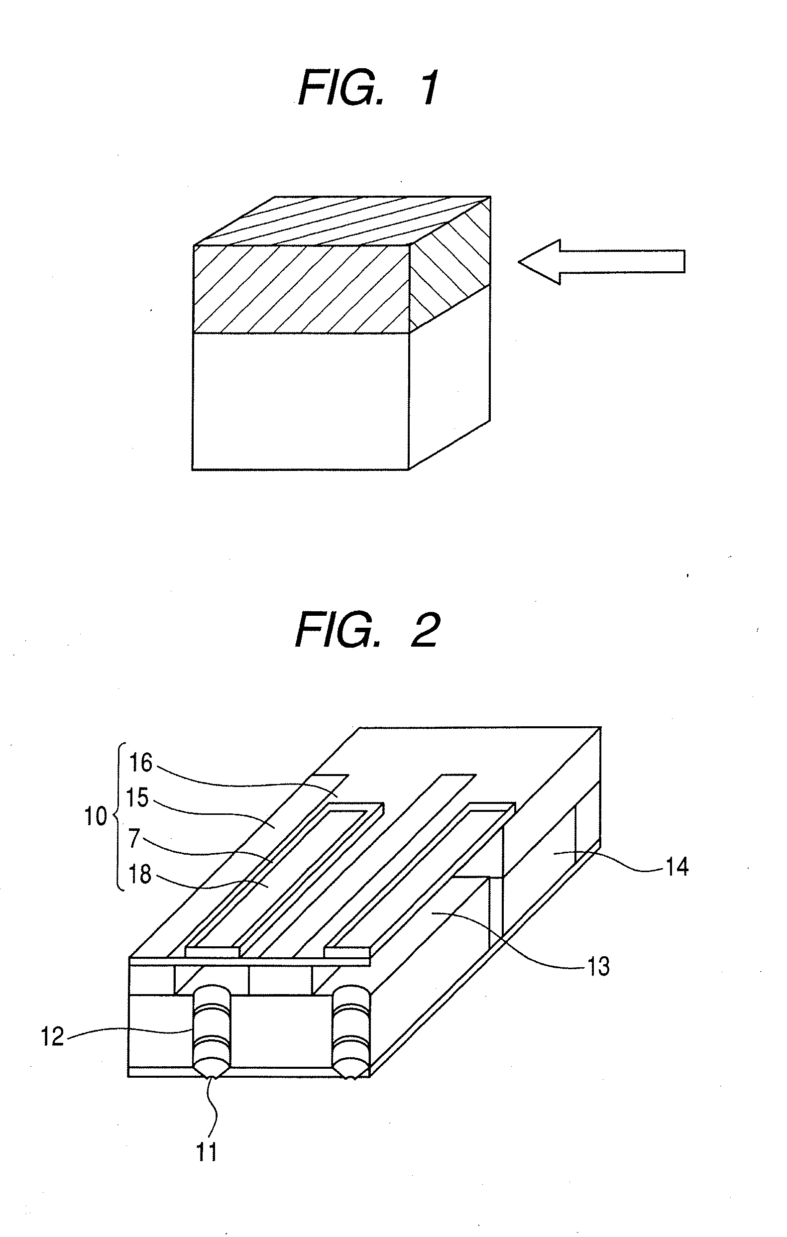
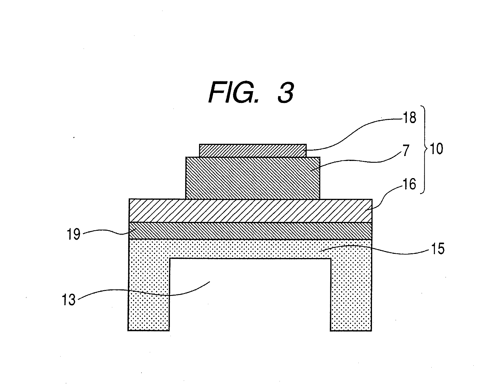
[0059] On an SrTiO3 (100) substrate of a thickness of 5 mm, an SrRuO3 (100) epitaxial layer, constituting a metal oxide electrode layer, was formed by rf-sputtering. Then a Pb(Zr, Ti)O3 epitaxial film was formed with a thickness of 3.0 μm, by a pulsed MO-CVD method, which is an MO-CVD method with an intermittent raw material gas supply, under raw material supply so as to obtain Zr / Ti ratio of 50 / 50. The film contained a mixture of tetragonal and rhombohedral, in which the tetragonal had a (100) / (001) orientation while the rhombohedral had a (100) orientation. The film forming conditions were changed, from a thickness of 0.8 μm, so as to increase the content ratio of the rhombohedral phase. The film forming conditions were changed by increasing each raw material gas supply time from 8 seconds to 15 seconds, by increasing the oxygen partial pressure, and increasing the revolution of the substrate from 6 rpm to 11 rpm. The epitaxial film was obtained under heating of the substrate at 6...

example 2

[0064] A substrate prepared by laminating, on a 4-inch SOI (100) substrate, YSZ (100), CeO2 (100), LaNiO3 (100) and SrRuO3 (100) in succession as buffer layers, was employed. The SOI substrate employed had an SOI (100) layer of 3.0 μm, and an SiO2 layer in box layer of 1.0 μm. A PZT film was formed by sputtering on the SrRuO3 electrode layer. The film formation was conducted with two targets which were a PbZrO3 target and a PbTiO3 target, in such a manner as to obtain a Zr / Ti ratio of 52 / 48. The film formation was conducted under heating of the substrate at 600° C., and, in order to change the mixing proportion of the crystal phases, the substrate-target distance was increased and the revolution of the substrate was increased when the thickness reached 0.4 μm. Finally obtained was a PZT film of a thickness of 2.5 μm. The composition of the film, measured in the same manner as in Example 1, was approximately constant, showing a change only within a variation range of ±1.5%. Also in R...

example 3

[0066] On an Si substrate having laminated layers YSZ / CeO2 / LaNiO3 / SrRuO3, a (Pb, La)TiO3 (PLT) epitaxial film was formed with a thickness of 1.2 μm as a clad layer by MO-CVD. Then a core layer of (Pb, La) (Zr, Ti)O3 (PLZT) (La / Zr / Ti composition ratio=8 / 65 / 35) was formed thereon with a thickness of 6 μm. In the course of film formation, the oxygen gas pressure and the substrate temperature among the film forming conditions were so changed, from a thickness of 1.3 μm, that the proportion of the tetragonal phase decreased. On the PLZT film, a clad PLT layer was formed in a similar manner as the aforementioned clad layer, and Cu—W was employed as a polarizing electrode to obtain an optical element. According to Raman spectroscopic measurement, the core layer was identified as a film in which the mixing proportion of the crystal phases started to change from a thickness of 1.3 μm. The film showed a higher proportion of tetragonal at the Si substrate side and a lower proportion at the pol...


PUM


Abstract

The invention is to provide an optical element satisfactory in transparency and characteristics as an optical modulation element, and a piezoelectric substance element satisfactory in precision and reproducibility as a fine element such as MEMS. The piezoelectric substance element includes, on a substrate, at least a first electrode, a piezoelectric substance film and a second electrode; wherein the piezoelectric substance film does not contain a layer-structured boundary plane; the crystal phase constituting the piezoelectric substance film comprises at least two of a tetragonal, a rhombohedral, a pseudocubic, an orthorhombic and a monoclinic; and the piezoelectric substance film includes, in a portion in which a change in the composition is within a range of ±2%, a portion where a proportion of the different crystal phases changes gradually in a thickness direction of the film.

Description

BACKGROUND OF THE INVENTION [0001] 1. Field of the Invention [0002] The present invention relates to a piezoelectric substance element, a liquid discharge head utilizing the same and an optical element. [0003] 2. Description of the Related Art [0004] Researches are being made in forming ferroelectric or dielectric materials into a thin film and utilizing it in a piezoelectric substance element such as MEMS or an optical element. Particularly researches are being actively made in forming a film of perovskite type oxides of ABO3 type and utilizing it as a device such as a piezoelectric substance element or an optical element, and attempts are being made in controlling the crystal orientation of the perovskite type oxide thereby improving the characteristics of device. [0005] For example Japanese Patent Application Laid-Open No. H06-350154 discloses a thin film of lead zirconate titanate (PZT) having a rhombohedral <111> orientation of 70% or higher within a compositional range n...

Claims


Application Information

Patent Timeline
IPC IPC(8): B05B1/08
CPCB41J2/14233H01L41/18B41J2202/03H10N30/8554
Inventor FUKUI, TETSUROTAKEDA, KENICHIAOKI, KATSUMIIFUKU, TOSHIHIROMATSUDA, TAKANORIFUNAKUBO, HIROSHIYOKOYAMA, SHINTAROKATODA, TAKASHINISHIDA, KEN
Owner CANON KK
Why Eureka
Try Eureka