Switch mode power converter having multiple inductor windings equipped with snubber circuits

a technology of power conversion circuit and switch mode, which is applied in the direction of electric variable regulation, process and machine control, instruments, etc., can solve the problems that the savings of 6w may not appear significant, and achieve the effect of reducing dv/d

Inactive Publication Date: 2007-09-20
ENERGY CONSERVATION TECH
View PDF26 Cites 29 Cited by
  • Summary
  • Abstract
  • Description
  • Claims
  • Application Information

AI Technical Summary

Benefits of technology

[0005]The present switch mode power converter having multiple inductor windings equipped with snubber circuits provides substantially complete, efficient, and economical solutions to the above problems by means of a small value inductor that has at least

Problems solved by technology

This 6W savings may not appear significant until one recognizes that a resistor that

Method used


Image

  • Switch mode power converter having multiple inductor windings equipped with snubber circuits
  • Switch mode power converter having multiple inductor windings equipped with snubber circuits
  • Switch mode power converter having multiple inductor windings equipped with snubber circuits

Examples


Embodiment Construction

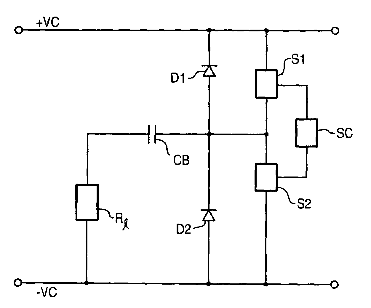
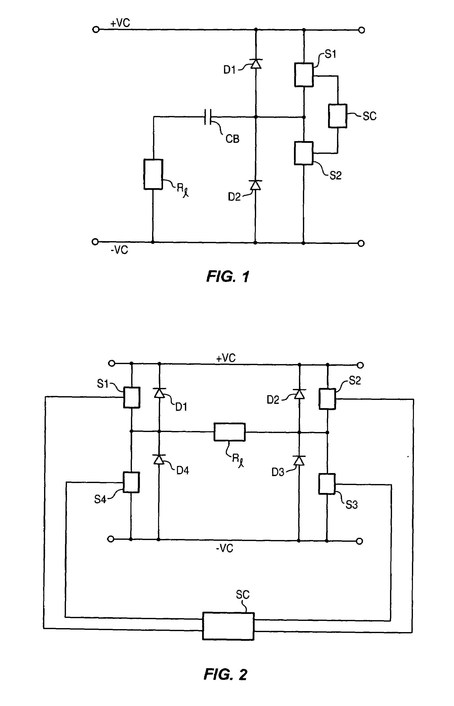
[0024]The most popular switch mode power converter topologies are fly-back, buck boost, forward, push-pull, half bridge, and full bridge power converters. Block diagrams of the two most commonly used topologies for high power applications are shown in FIGS. 1 and 2, where FIG. 1 is for a half bridge inverter and FIG. 2 is for a full bridge inverter. In FIG. 1, the semiconductor power switches S1 and S2 are alternately turned ON and OFF. A switch mode control circuit SC, such as model SG 2525 made by ST Microelectronics, governs the switching speeds, that is, the operating frequencies of the inverter and duty cycles. In FIG. 1, the capacitor CB is a DC blocking capacitor and 14 is the switched load such as a resonant LC network or a transformer. The diodes D1 and D2 are commutating diodes. The full bridge inverter of FIG. 2 consists of four power switches S1-S4. The power switches S1 and S3 form the first pair and the power switches S2 and S4 form the second pair, whereby when the fi...


PUM


Abstract

The present switch mode power converter having multiple inductor windings equipped with snubber circuits uses a small value inductor that has at least one properly oriented secondary winding, and ultra fast diodes interconnect the primary and the secondary windings of this inductor for providing protection against momentary short circuits, reductions of dv/dt, and switching losses.

Description

CROSS-REFERENCE TO RELATED APPLICATIONS[0001]This application is a continuation-in-pant of U.S. patent application Ser. No. 11 / 375,558 filed on Mar. 14, 2006.FIELD OF THE INVENTION[0002]This invention relates to single stage power conversion circuitry used in switch mode inverters and power converters.BACKGROUND OF THE INVENTION[0003]For increased efficiency and size reductions, switch mode power converters and inverters use high frequency switching techniques for power conversions. However, high frequency switching of power switches creates many undesirable circuit behaviors such as switch turn-on and turn-off losses, high voltage switching transient noise, and momentary short circuits of power switches. The results are often catastrophic, such as device failures, excessive heat generation within the power devices, and unwanted electromagnetic interference EMI). Solutions to these problems are complex and often at the expense of reduced power conversion efficiency, increased size, ...

Claims


Application Information

Patent Timeline
IPC IPC(8): G05F1/00
CPCH02M1/34
Inventor QUAZI, FAZLE S.
Owner ENERGY CONSERVATION TECH
Why Eureka
Try Eureka