
System and Method For Image Reconstruction

a technology of image reconstruction and system, applied in the field of image reconstruction, can solve the problems of limiting restricting the number and quality of projection measurements, and non-iterative reconstruction algorithms that do not typically handle the limited projection measurements well, and achieves the effect of convergence and accurate results

Inactive Publication Date: 2007-09-20
SIEMENS MEDICAL SOLUTIONS USA INC
View PDF9 Cites 37 Cited by
  • Summary
  • Abstract
  • Description
  • Claims
  • Application Information

AI Technical Summary

Benefits of technology

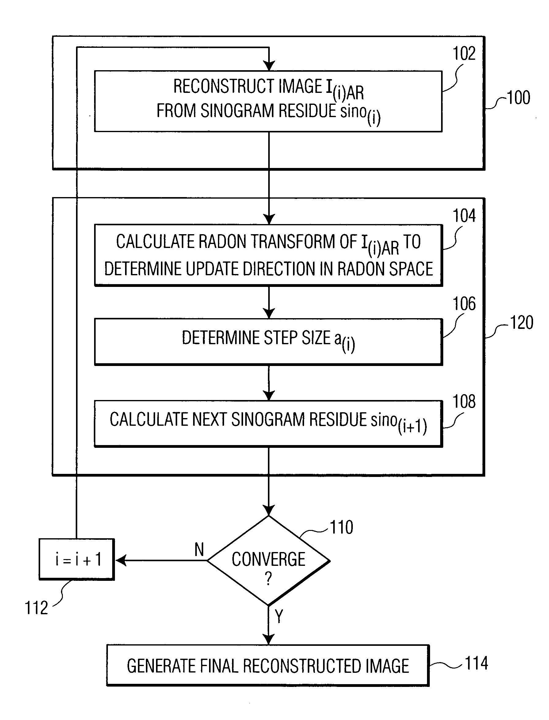
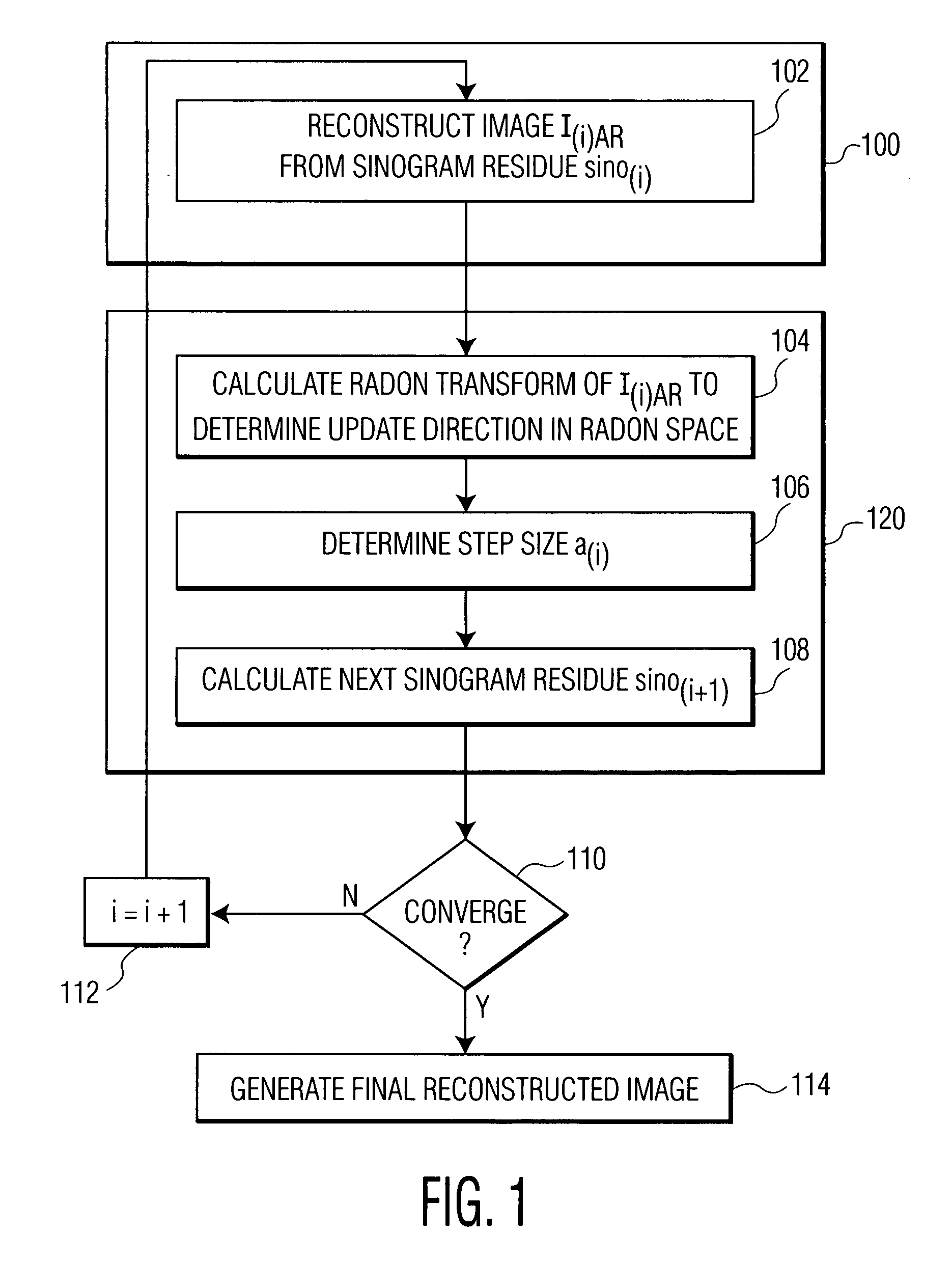
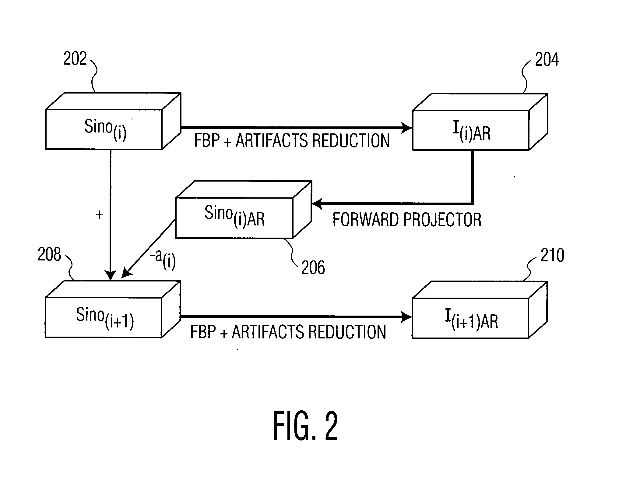
[0007] In one embodiment of the present invention, adaptive filtering in the image space is performed to generate an artifact-reduced reconstructed image of the current sinogram residue. This artifact-reduced reconstructed image of the current sinogram residue represents an update or descent direction in the image space. The adaptive filtering regularizes the reconstructed image of the current sinogram residue based on prior constraints. The update direction is transformed into the Radon space, and a step size is determined which minimizes a difference between the current sinogram residue and a Radon transform of the artifact-reduced reconstructed image of the current sinogram residue in the Radon space. The minimized difference between the current sinogram residue and a Radon transform of the artifact-reduced reconstructed image of the current sinogram residue is the next sinogram residue. These steps may be repeated iteratively for each next sinogram residue until the solution converges. A final reconstruction result (image) is generated by combining artifact-reduced reconstructed images generated for each sinogram residue.

Problems solved by technology

In practice, the number and the quality of the projection measurements is often limited, which effects the quality of the images reconstructed from the projection measurements.
For example, in medical imaging, low-dose diagnostic tomographic imaging is commonly used to reduce the risks of excessive radiation to a patient, and can greatly restrict the number and quality of projection measurements.
Non-iterative reconstruction algorithms do not typically handle the limited projection measurements well, and often produce significant streaking artifacts.
However, applying prior knowledge of image shapes and borders in the null space of the projections is typically very difficult.
The derivative on the data fidelity term results is a back projection in each iteration, which typically provides blurry results and converges slowly.
Furthermore, the step size to update in the gradient-descent direction is usually set small due to convergence issues, which further increases the number of iterations necessary for convergence significantly.

Method used


Image

  • System and Method For Image Reconstruction
  • System and Method For Image Reconstruction
  • System and Method For Image Reconstruction

Examples


Embodiment Construction

[0015] The present invention is directed to a method for tomographic image reconstruction. The present invention can be applied to any medical imaging technology, including computed tomography (CT), magnetic resonance imaging (MRI), etc. Embodiments of the present invention are described herein to give a visual understanding of the signal downsizing method. It is to be understood, that these embodiments may be performed within a computer system using data stored within the computer system. Accordingly, some steps of the method can occur as internal representations within the computer system.

[0016] Traditional iterative image reconstruction methods discretize the Radon transform operator to form weight factors between each image pixel intensity and each sinogram value. This set of weight factors is represented as the system matrix A, and represents the forward projection from the image to the sinogram. By stacking the known sinogram values into a vector b, the reconstruction problem...


PUM


Abstract

A system and method for image reconstruction is disclosed. The method divides iterative image reconstruction into two stages, in the image and Radon space, respectively. In the first stage, filtered back projection and adaptive filtering in the image space are combined to generate a refined reconstructed image of a sinogram residue. This reconstructed image represents an update direction in the image space. In the second stage, the update direction is transformed to the Radon space, and a step size is determined to minimize a difference between the sinogram residue and a Radon transform of the refined reconstructed image of the sinogram residue in the Radon space. These stages are repeated iteratively until the solution converges.

Description

[0001] This application claims the benefit of U.S. Provisional Application No. 60 / 783,177, filed Mar. 16, 2006, the disclosure of which is herein incorporated by reference.BACKGROUND OF THE INVENTION [0002] The present invention relates to image reconstruction, and more particularly to tomographic image reconstruction in medical imaging. [0003] Tomographic image reconstruction refers to reconstructing an image from a set of projection measurements that are described by a Radon transform. The Radon transform provides a mathematical basis for reconstructing tomographic images from measured projection data. The Radon transform of an image is commonly referred to as a sinogram. Tomographic image reconstruction reconstructs an image by determining pixel values based on the sinogram of the projection data. This is described in greater detail in A. Kak and M. Slaney, Principles of Computerized Tomographic Images, IEEE Press, 1988. [0004] In practice, the number and the quality of the proje...

Claims


Application Information

Patent Timeline
IPC IPC(8): H05G1/60A61B6/00G01N23/00G21K1/12
CPCG01N23/046G06T11/006G01N2223/419G06T2211/424G06T2211/421
Inventor CHEN, YUNQIANGCHENG, LINFANG, TONGTYAN, JASON
Owner SIEMENS MEDICAL SOLUTIONS USA INC
Learn More