Passive Optical Network System and Method for Protecting the Services of the Same

a passive optical network and optical network technology, applied in the field of optical network, can solve the problems of affecting user services, affecting the security of the system, and unable to protect and recover from failures, so as to reduce construction costs and improve bandwidth utilization. the effect of utilization

Active Publication Date: 2007-09-20
HUAWEI TECH CO LTD
View PDF6 Cites 18 Cited by
  • Summary
  • Abstract
  • Description
  • Claims
  • Application Information

AI Technical Summary

Benefits of technology

[0010]The embodiment of the present disclosure provides a PON system and a service protection method that is capable of service protection and fault diagnosis when a link or equipment fault occurs in the PON system. The PON system and service protection method have reduced construction cost and improved bandwidth utilization.
[0016]Compared with the prior art, the embodiments of the present disclosure have the following effects:
[0017]1. One backup link is added between any two equipment without the need to add redundant equipment, thereby improving network security while greatly reducing the construction cost.
[0018]2. A backup link is added between any two equipment without an additional redundant service channel, thereby avoiding resource waste and improving bandwidth utilization.

Problems solved by technology

However, a pure tree topology does not have measures for failure protection and recovery or means for locating a failure.
If an equipment or link fault is not corrected for a long time, the user services may be greatly affected and security may be seriously impaired.
It is also very difficult to locate the fault.
1. High construction cost. Each ONU requires two sets of identical transmission equipment requires an additional optical interface, which results in a dramatic increase in the ONU cost.
2. Low bandwidth utilization. Only one of the two work channels is working while the other one is always idle, resulting in an increased waste of resources.
3. Inability to locate a fault and indicate fault type.

Method used


Image

  • Passive Optical Network System and Method for Protecting the Services of the Same
  • Passive Optical Network System and Method for Protecting the Services of the Same
  • Passive Optical Network System and Method for Protecting the Services of the Same

Examples


Embodiment Construction

[0026]The preferred embodiments of the present disclosure are described in details below in conjunction with drawings.

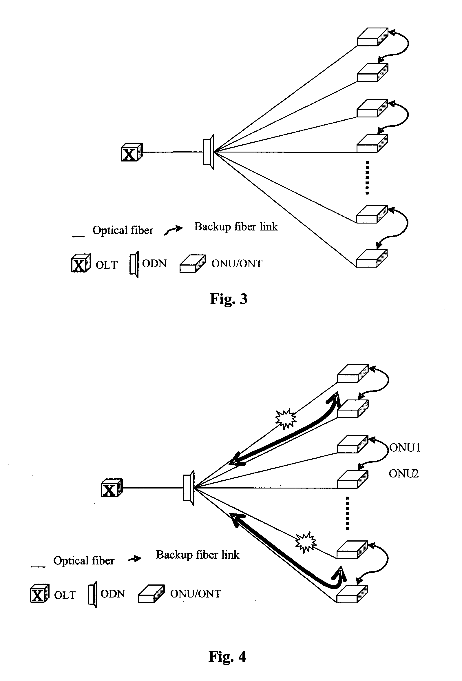
[0027]FIG. 3 is a schematic drawing showing the networking of the PON system of an embodiment of the present disclosure, in which the ONU / ONT equipment is connected to the ODN equipment via an optical fiber and the ODN equipment is connected to the OLT equipment via an optical fiber. The user service data is connected via the ONU / ONT, gathered on the ODN, and is then sent to the OLT for further processing. The ONU / ONT equipment that needs protection is grouped into a protection group, and the pieces of equipment within this group are interconnected to each other via a backup link. In this embodiment, two pieces of equipment are grouped into a protection group, and the two pieces of equipment within the protection group are interconnected via a backup link to form a mutual protection relationship, where the protection group details are recorded in the OLT.

[0028]The fo...


PUM


Abstract

The present disclosure provides a passive optical network (PON) system and a method for protecting the service of the system for service recovery and fault locating in case of a failure of the network, wherein the PON system comprises an optical line terminal (OLT), an optical distribution network (ODN) and an optical network terminal (ONT) equipment protection group comprising a plurality of ONT equipment groups, each of which is connected to at least one of other ONT equipment groups within the ONT equipment protection group for the mutual protection relationship. The PON system of the present disclosure does not require equipment and link redundancy for backup, contributes to reduced cost and improved utilization of resources, and provides a means for diagnosing any faults of the links and equipment in the network.

Description

CROSS-REFERENCE TO RELATED APPLICATIONS[0001]This application is claiming priority of Chinese Application No. 200610034310.0 filed Mar. 15, 2006, entitled “Passive Optical Network System and Method for Protecting the Services of the Same” which application is incorporated by reference herein in its entirety.BACKGROUND OF THE DISCLOSURE[0002]The present disclosure relates generally to the optical network field, and more particularly to a PON system and method for protecting its services.[0003]A Passive Optical Network, or PON, is an optical fiber cabling network accessed by a user in which the central part contains no active electronic devices and all of the user signals converge going upstream and are broadcast going downstream using only passive components, such as optical dividers. Passive optical network technology is a broadband access technology that has great competitive advantages and is an important technical means that offers user access over the “the last mile”. By using p...

Claims


Application Information

Patent Timeline
Patent Type & Authority Applications(United States)
IPC IPC(8): H04B10/00H04B10/272
CPCH04J3/14H04Q2011/0081H04Q11/0067H04J3/1694
Inventor GAO, HAIZHENG, GANG
Owner HUAWEI TECH CO LTD
Why Eureka
Try Eureka