
Image forming apparatus, process cartridge and toner for use in the image forming apparatus

Active Publication Date: 2007-09-20
RICOH KK
View PDF45 Cites 54 Cited by
  • Summary
  • Abstract
  • Description
  • Claims
  • Application Information

AI Technical Summary

Benefits of technology

[0067]Therefore, even when a toner having a volume average particle diameter of greater than 5.0 μm and less than 5.5 μm, a SF-1 / SF-2 ratio of greater than 1.00 and less than 1.15 and including toner particles having a particle diameter of not greater than 4.0 μm in an amount of not less than 20% by number is used, the toner has good cleanability if the toner satisfies the relationship (4). Therefore, high quality images having good fine dot reproducibility can be produced without causing the defective cleaning problem. In addition, the toner has good transferability. Thus, a toner and an image forming apparatus having good reliability in cleanability can be provided.

Problems solved by technology

In contrast, tandem-type image forming apparatuses have an advantage of high speed printing but have a relatively high cost.
However, small toners and spherical toners tend to have a drawback in that residual toner particles present on the surface of an image bearing member escape through a cleaning blade, resulting in defective cleaning (i.e., resulting in occurrence of a background development problem in that the background of an image is soiled with toner particles).
When a high pressure is applied to a cleaning blade to prevent such a problem, an excessive shearing force is applied to a portion of the blade, thereby causing chipping (i.e., omission of a portion) of the cleaning blade, resulting in occurrence of defective cleaning.
Alternatively, problems in that the cleaning blade and / or the image bearing member are seriously abraded occur.
When a cleaning blade is seriously abraded, the area of the contact point between the blade and the image bearing member increases, resulting in decrease of the pressure of the cleaning blade to the image bearing member.
Therefore, a problem in that small toners or spherical toners cannot be well removed from the image bearing member occurs.
Thus, it is hard to well remove a small-size toner or a spherical toner.
(1) When an excessive amount of lubricant is applied to an image bearing member, the charging roller contacted with the image bearing member is contaminated, thereby causing defective charging, resulting in formation of abnormal images.
(2) Since the lubricant applied to an image bearing member is mixed with the developer used, the toner in the developer is prevented from being well charged, and thereby electrostatic latent images on the image bearing member cannot be well developed, resulting in formation of abnormal images.
(3) Setting of a lubricant applicator in an image forming apparatus increases the size and costs of the apparatus.
Thus, a technique of controlling application of a lubricant to an image bearing member has not yet established.
Namely, when a lubricant applicator is provided in an image forming apparatus, various problems are caused.
However, when a small-size spherical toner is used to produce high quality images, toner particles on an image bearing member are not often removed well (i.e., the toner has a low margin for cleanability) because such toner tends to include fine toner particles (having a volume particle diameter of not greater than 4 μm) in an amount of not less than 20% by number.
However, performing such a classification operation increases costs and production time of the toner while decreasing yield.

Method used


Image

  • Image forming apparatus, process cartridge and toner for use in the image forming apparatus
  • Image forming apparatus, process cartridge and toner for use in the image forming apparatus
  • Image forming apparatus, process cartridge and toner for use in the image forming apparatus

Examples


example 1

(Preparation of Unmodified Polyester Resin)

[0257]The following components were contained in a reaction vessel equipped with a condenser, a stirrer and a nitrogen feed pipe to perform a polycondensation reaction for 8 hours at 230° C. under normal pressure.

Ethylene oxide (2 mole) adduct of229 partsbisphenol APropylene oxide (3 mole) adduct of529 partsbisphenol ATerephthalic acid208 partsAdipic acid 46 partsDibutyltin oxide 2 parts

[0258]Then the reaction was further continued for 5 hours under a reduced pressure of from 10 to 15 mmHg (1332 to 1998 Pa).

[0259]Further, 44 parts of trimellitic anhydride was added to the vessel to be reacted with the reaction product for 2 hours at 180° C. under normal pressure. Thus, an unmodified polyester resin was prepared. It was confirmed that the unmodified polyester resin has a number average molecular weight of 2500, a weight average molecular weight of 6700, a glass transition temperature (Tg) of 43° C. and an acid value of 25 mgKOH / g.

(Preparatio...

example 2

[0295]The procedure for preparation of the toner in Example 1 was repeated except that the added amount of the modified layered inorganic material (CLAYTON APA) was changed from 3 parts to 0.1 parts. Thus, a toner of Example 2 was prepared. The properties of the toner are shown in Table 1.

example 3

[0296]The procedure for preparation of the toner in Example 1 was repeated except that the modified layered inorganic material (CLAYTON APA) was changed to another layered montmorillonite (CLAYTON HY from Southern Clay Product), in which at least a part of the interlayer ions is modified by an ammonium salt having polyoxyethylene group. Thus, a toner of Example 3 was prepared. The properties of the toner are shown in Table 1.


PUM

PropertyMeasurementUnit
Temperatureaaaaaaaaaa
Lengthaaaaaaaaaa
Lengthaaaaaaaaaa

Abstract

An image forming apparatus including an image bearer; a charging device charging the image bearer; a light irradiating device irradiating the charged image bearer with light to form an electrostatic image; a developing device developing the electrostatic image with a developer including a toner to form a toner image on the image bearer; a transfer device transferring the toner image; and a cleaning device cleaning the image bearer, wherein the volume average particle diameter of the toner is greater than 5.0 μm and less than 5.5 μm, the content of toner particles having a particle diameter of not greater than 4.0 μm is not higher than 20% by number, the ratio of the first shape factor SF-1 to the second shape factor SF-2 is from 1.00 to 1.15, and the content of toner particles having a SF-2 of not less than 115 is not less than 67.8% by number.

Description

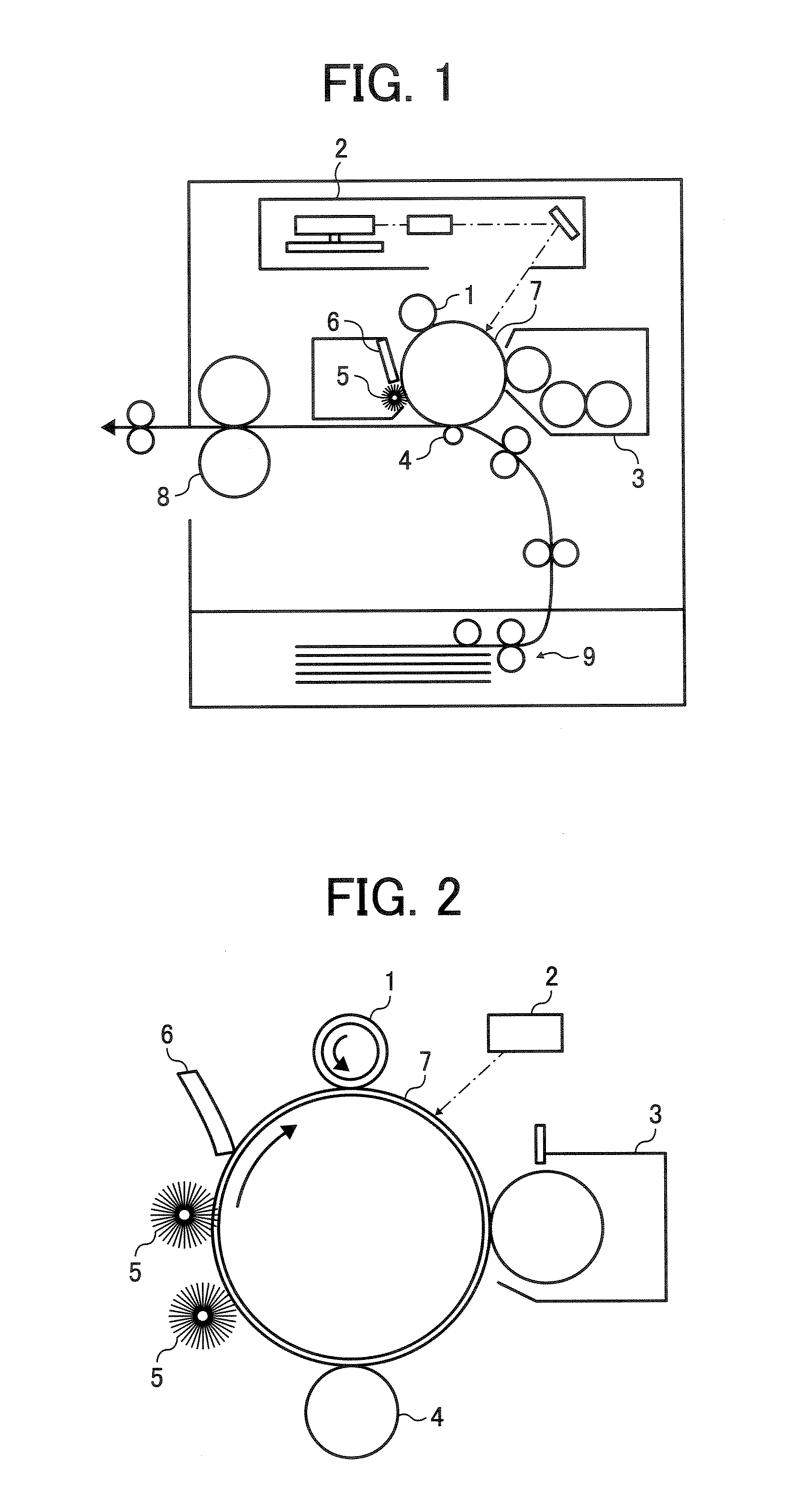
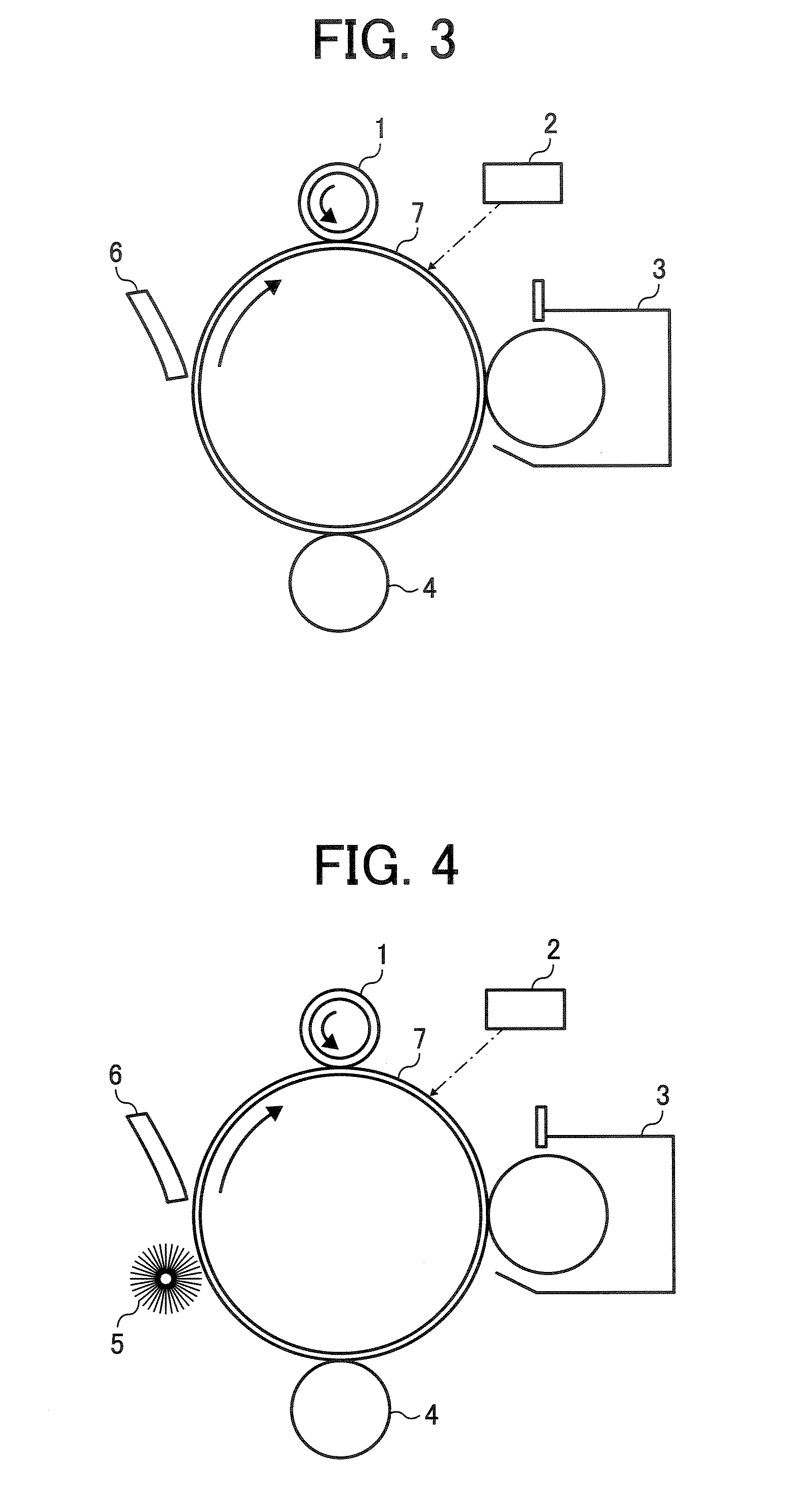
BACKGROUND OF THE INVENTION[0001]1. Field of the Invention[0002]The present invention relates to an image forming apparatus, and more particularly to an image forming apparatus having an image bearing member, a charging device, a developing device, a transfer device and a cleaning device. In addition, the present invention also relates to a toner for use in the image forming apparatus, and a process cartridge.[0003]2. Discussion of the Background[0004]Electrophotographic image forming methods have been used for various fields. Electrophotographic image forming methods typically include the following processes.(1) charging the surface of an image bearing member such as photoreceptors (charging process):(2) irradiating the charged image bearing member with light to form an electrostatic latent image on the image bearing member (light irradiating process);(3) developing the electrostatic latent image with a developer including a toner to form a toner image on the image bearing member (...

Claims


Application Information

Patent Timeline
IPC IPC(8): G03G9/087
CPCG03G9/0806G03G9/0819G03G9/0821G03G9/0926G03G9/08755G03G9/08793G03G9/09G03G9/0827
Inventor SESHITA, TAKUYASAWADA, TOYOSHISUZUKI, TOMOMINAGATOMO, TSUNEYASUKOJIMA, SATOSHI
Owner RICOH KK
Learn More