Vehicle simulator environment

a simulator environment and vehicle technology, applied in the field of vehicle simulator environment, can solve the problems of difficult swap between the use of a simulator for one purpose, and a tight tolerance for the degree of programming required, so as to avoid the need for complex mechanical structure or difficult to program software and firmwar

a simulator environment and vehicle technology, applied in the field of vehicle simulator environment, can solve the problems of difficult swap between the use of a simulator for one purpose, and a tight tolerance for the degree of programming required, so as to avoid the need for complex mechanical structure or difficult to program software and firmwar

US20070218427A1Inactive Publication Date: 2007-09-20LEFTON NORMAN

Image

  • Vehicle simulator environment
  • Vehicle simulator environment
  • Vehicle simulator environment

Examples


Embodiment Construction

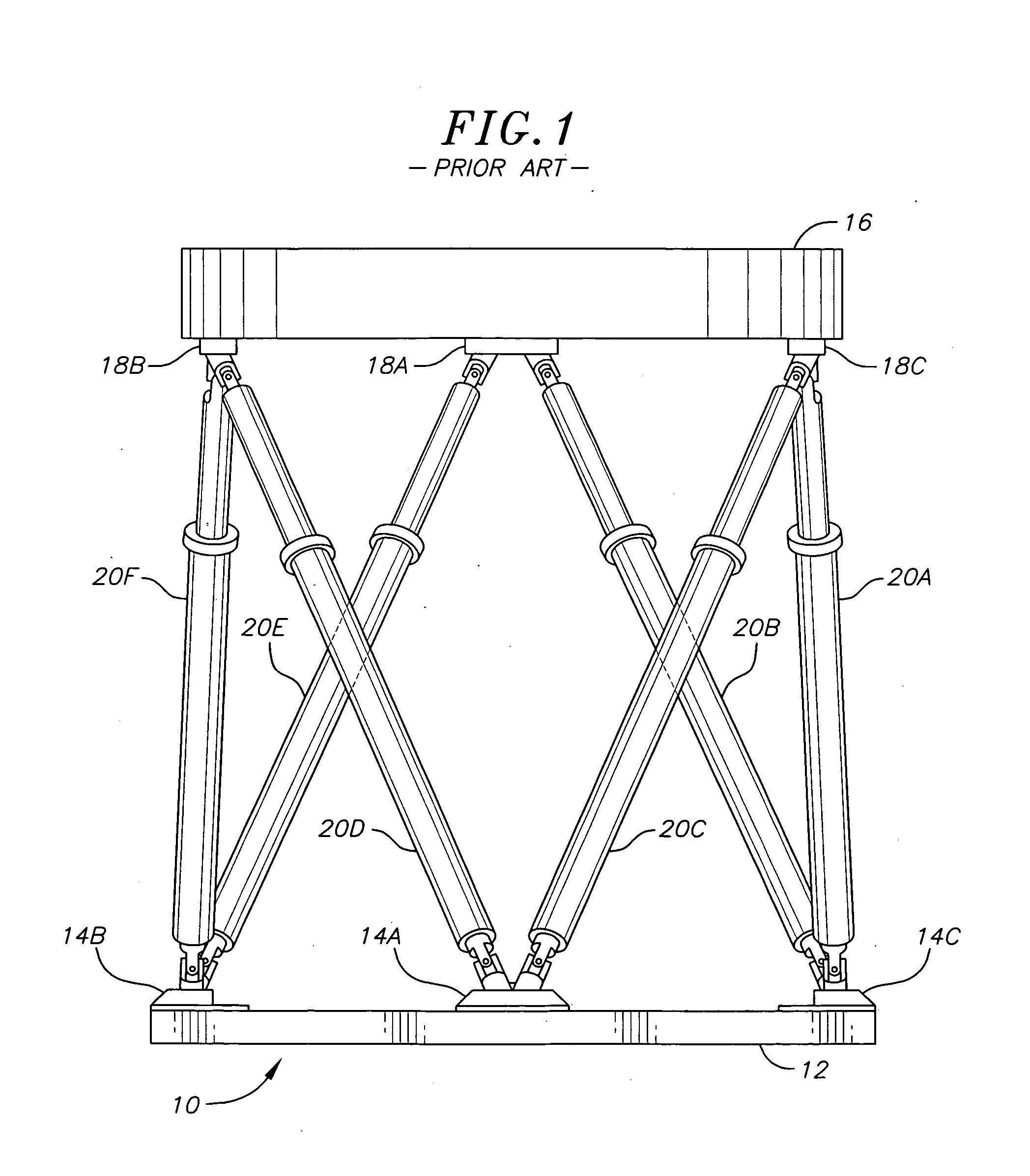
[0015] Referring to FIG. 1, there is shown a prior art motion base 10, which has a base portion 12 with three lower anchors, 14A, 14B and 14C, a floating platform portion 16 with upper anchors 18A, 18B and 18C. Six hydraulic or electric cylinders 20A through 20F connected between the lower anchors 14A, 14B and 14C to the upper anchors 18A, 18B and 18C of the floating platform 16. Cylinder 20A connects at its bottom via a universal joint to anchor 14C and at its top to the anchor 18C, also with a universal joint or other pivot. Cylinder 20B connects at its bottom portion to anchor 14C and at its top to anchor 18A by a universal joint or other pivot. The other cylinders are similarly connected. Cylinder 20C connects at its bottom portion to anchor 14A and at its top to anchor 18C. Cylinder 20D connects at its bottom portion to anchor 14A and to its top to anchor 18B. Cylinder 20E connects at its bottom portion to anchor 14B and connects to anchor 18A at its top. Lastly, cylinder 20F c...


PUM


Abstract

The invention is a vehicle simulator operator environment. The vehicle simulator operator environment has a plurality of ports, which plurality of ports are adapted to engage with simulator control devices and / or displays that corresponds to a vehicle to be simulated. By engaging a predetermined set of control devices and / or displays that correspond to a particular vehicle to be simulated with a predetermined set of ports, the vehicle simulator will be operable as a vehicle simulator for the particular simulated vehicle.

Description

CROSS-REFERENCE TO RELATED APPLICATION(S) [0001] This application claims the benefit of U.S. Provisional Patent Application No. 60 / 736,743, entitled “Vehicle Simulator”, filed on Nov. 14, 2005.SUMMARY OF THE INVENTION [0002] Vehicle Motion Simulators have been available for many decades and are used for a variety of purposes including for training of operators of military and commercial motor vehicles, heavy machinery and aircraft. For example, there are variety of flight simulators for helicopters, jets and propeller aircraft, as well as driver training simulators for trucks, boats, tanks and trains, gunnery training simulators for tanks, wheeled vehicles and boats, mission training simulators for rescue crew and drivers, and industrial simulators and material handling equipment training simulators. In addition to these uses, simulators are used in the entertainment field for a variety of amusement park rides, in museums, in video arcades, etc. [0003] Regardless of their applicatio...

Claims


Application Information

Patent Timeline
20 Sep 2007
Publication
US20070218427A1
IPC
G09B9/02
CPC
A63G31/16; G09B9/02; G09B19/16; G09B9/05; G09B9/16; G09B9/04
Inventors
LEFTON, NORMAN