

Silicone adhesive composition and method for preparing the same
a technology of adhesive composition and silicon, applied in the direction of mixing, solid balls, sports equipment, etc., can solve the problems of reducing the thermodynamic driving force of heat removal, reducing the ability to transfer heat through the interface between the surfaces, and reducing the temperature between the device and the ambient temperature, so as to reduce the cure temperature and improve the adhesion. , the effect of improving the cure ra
- Summary
- Abstract
- Description
- Claims
- Application Information
AI Technical Summary
Benefits of technology
Problems solved by technology
Method used
Image

Examples
example 1
[0070]Two separate thermally conductive fillers were used in this formulation. The first filler was Denka DAW-05 alumina filler having an average particle size of 5 μm and a maximum particle size of 24 μm and the second filler was Sumitomo's AA-04 alumina filler having an average particle size of 0.4-0.6 μm and a maximum of about 1 μm. The thermally conductive fillers (604.30 parts total (483.58 parts of the first filler and 120.72 parts of the second filler)) were mixed in a lab scale Ross mixer (1 quart capacity) at approximately 18 rpm for 2.5 hours at 140-160° C. The fillers were then cooled to 35-45° C., brought to atmospheric pressure and 100 parts of vinyl-stopped polydimethylsiloxane fluid (350-450 cSt, approximately 0.48 weight percent vinyl; SL6000-D1 from GE Silicones) along with 0.71 parts of a pigment masterbatch (50 weight percent carbon black and 50 weight percent of a 10,000 cSt vinyl-stopped polydimethylsiloxane fluid; M-8016 from GE Toshiba) and a portion of the hy...
example 3
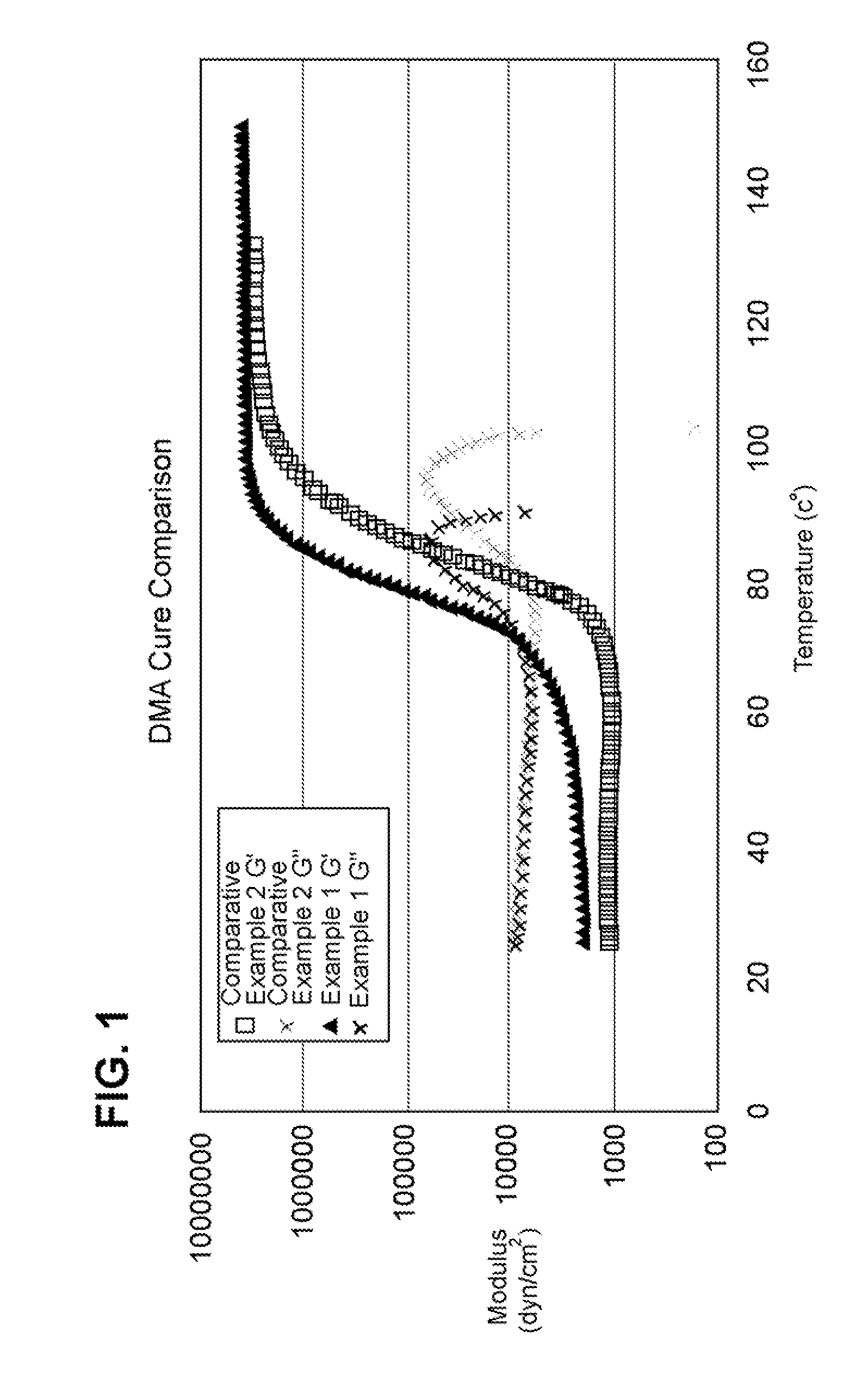
[0072]Dynamic mechanical analysis (DMA) was completed using a TA Instruments Ares-LS2 to compare gelation points for the two samples (Example 1 vs. Comparative Example 2) as temperature ramped from 25° C. to 150° C. at a rate of 2 degrees C. per minute with a parallel plate geometry. See Table 1 and FIG. 1.
[0073]The storage (elastic) modulus, G′, scales directly with molecular weight in polymeric systems. As cure begins, the molecular weight increases, and the G′ value increases. When G′ curves are compared for Example 1 and Comparative Example 2, the increase in G′ for the Example 1 sample is shown to occur at a much lower temperature than the Comparative Example 2 sample. The slope of the G′ line is positive for the Example 1 sample, starting at about 30° C. In contrast, the slope of the G′ curve for the Comparative Example 2 sample remains at zero until approximately 65° C. This difference highlights the fact that the Example 1 sample begins its curing reaction at a much lower te...
example 4
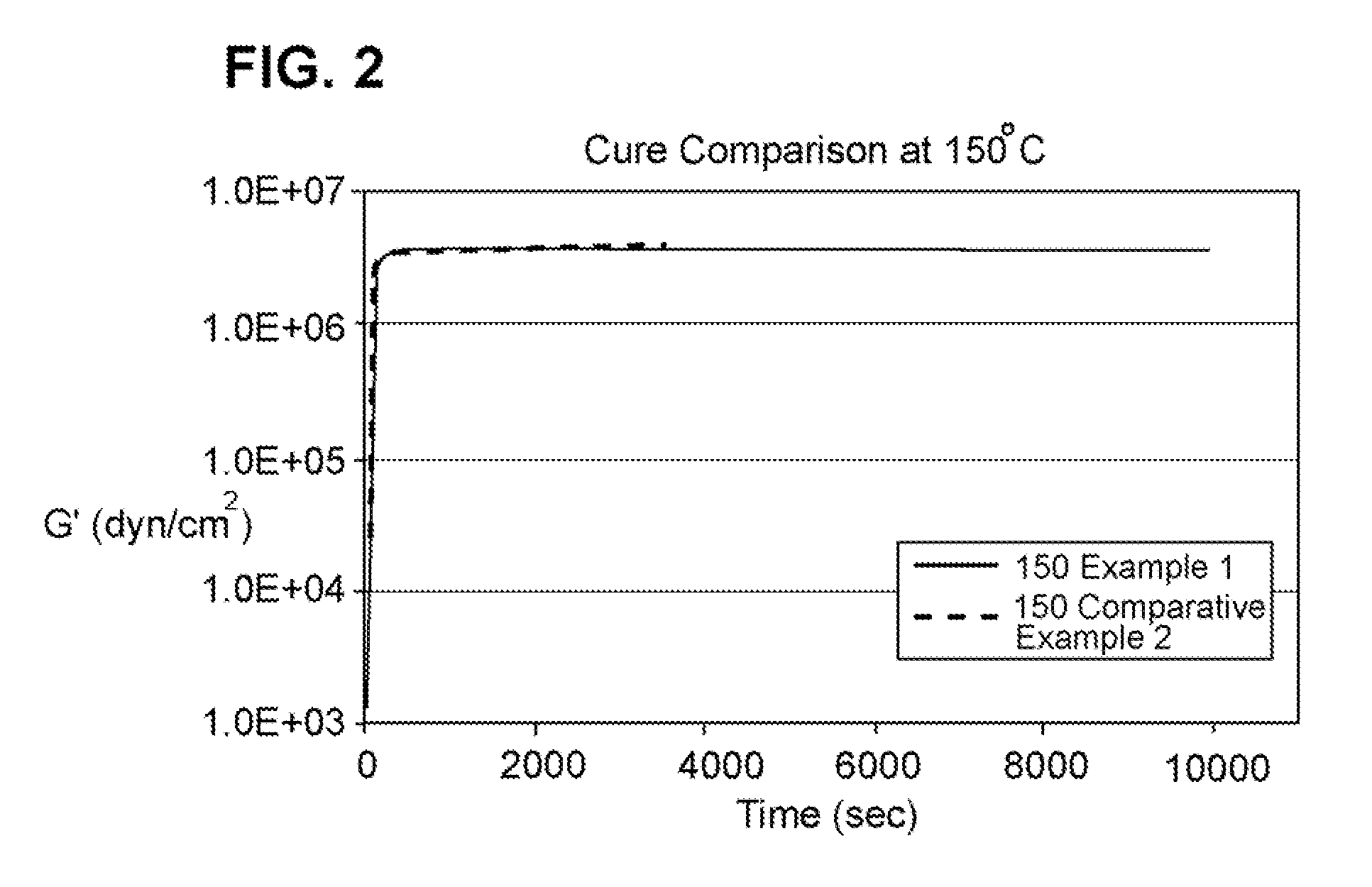
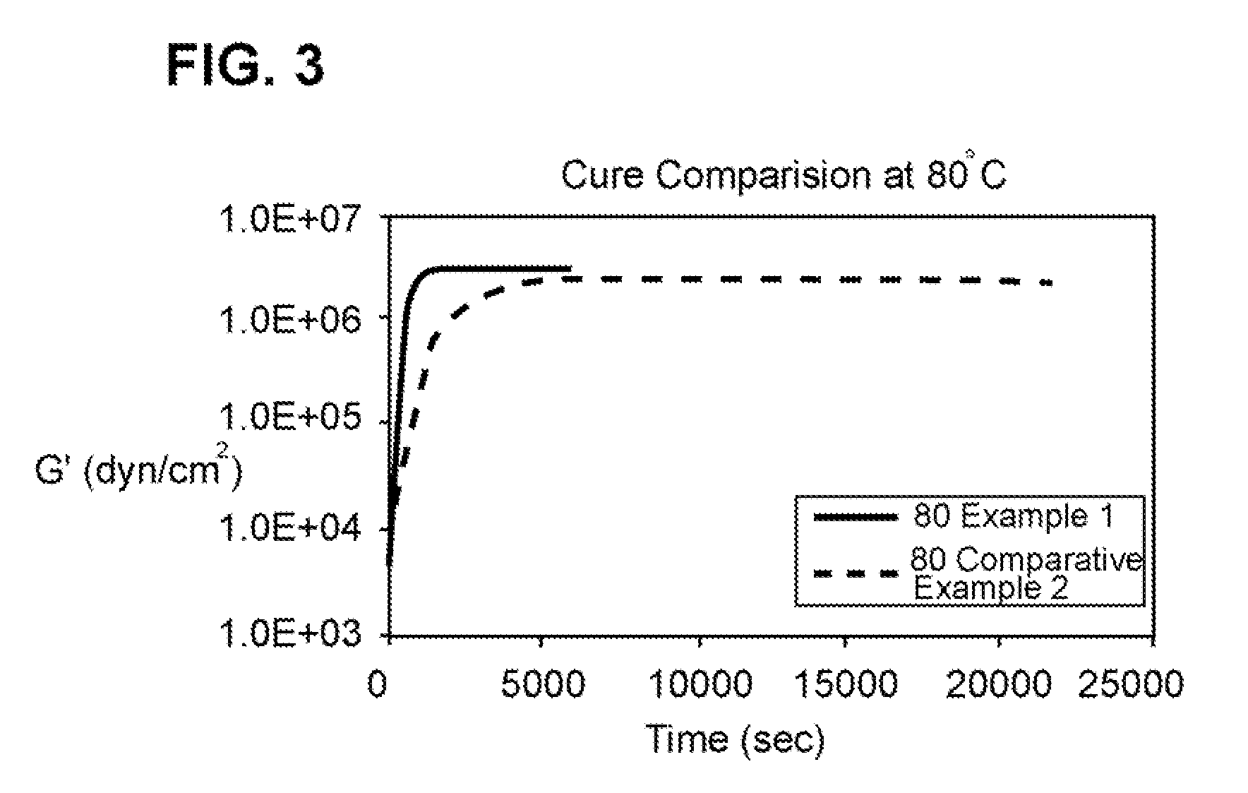
[0076]This example tested the time required to achieve full cure as a function of different cure temperatures. The G′G″ crossover point indicates onset of cure and full cure is indicated by a plateau in the storage modulus (G′) in a DMA experiment. Table 2, below, shows that the final G′ value at the end of the isothermal hold (final G′) is essentially the same as the maximum G′ value (maximum G′) attained throughout each of the runs. The maximum G′ value was used for the calculations to determine the extent of cure.
[0077]Table 2 shows that the maximum G′ value for the Example 1 sample is reduced by only 8% when the cure temperature is reduced from 150° C. to 80° C. This same reduction in cure temperature for the Comparative Example 2 sample results in a reduction of 26% in the maximum G′ value. A lower plateau value for G′ indicates a reduction in crosslink density. The larger the reduction in G′, the larger the reduction in crosslink density and the less cured the material is. The...
PUM
| Property | Measurement | Unit |
|---|---|---|
| Fraction | aaaaa | aaaaa |
| Fraction | aaaaa | aaaaa |
| Percent by mass | aaaaa | aaaaa |
Abstract
Description
Claims
Application Information