

Intra-operative 3-D reconstruction of bone cement boli using X-rays
- Summary
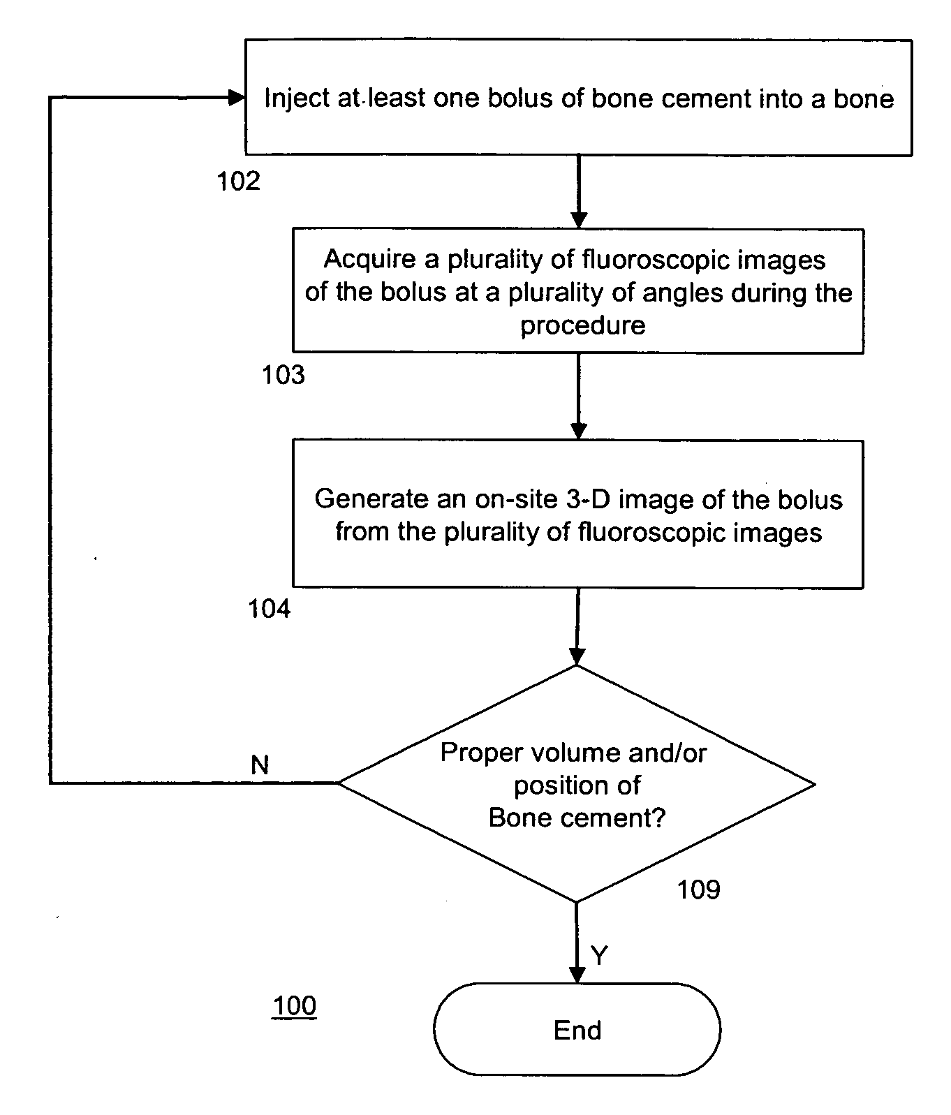
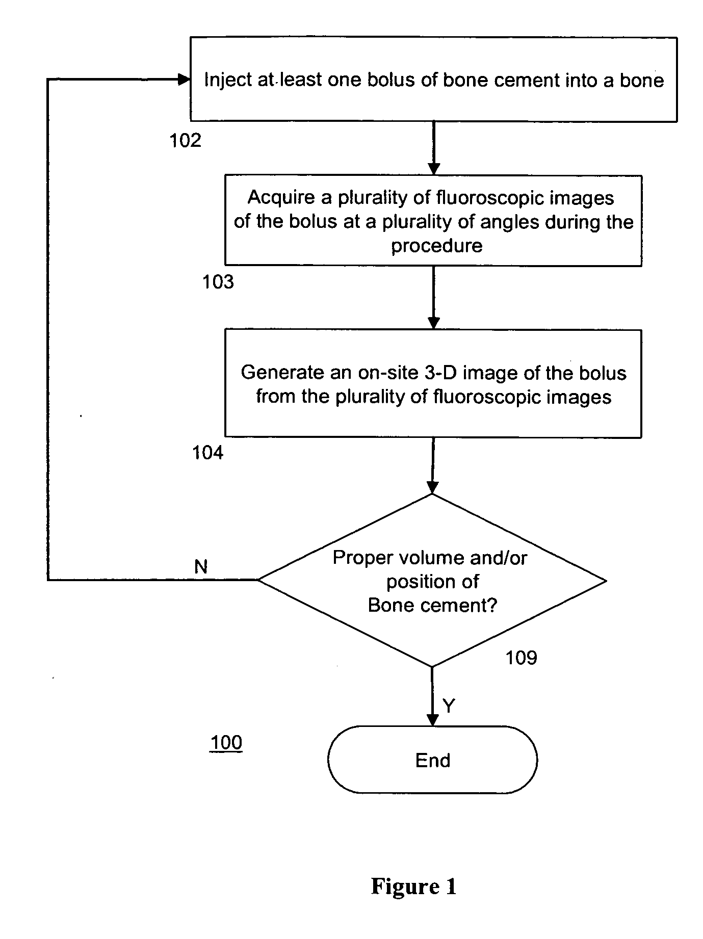
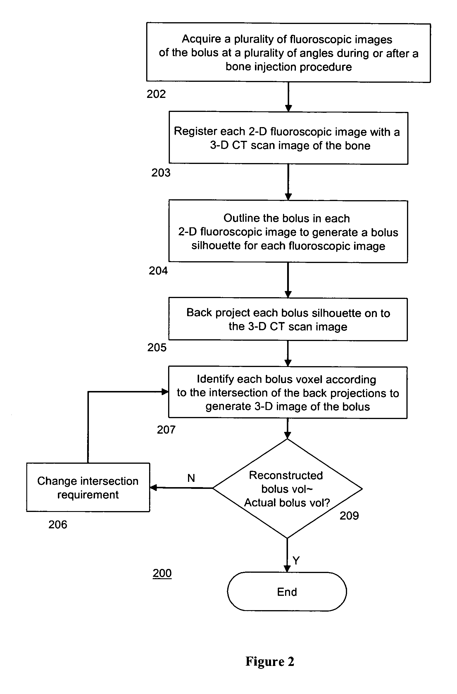
- Abstract
- Description
- Claims
- Application Information
AI Technical Summary
Benefits of technology
Problems solved by technology
Method used
Image

Examples
example
[0046] Six cadaveric spinal segments (T9-L4; Male, ages 63-88) from a coinciding study were analyzed. They were placed two at a time in a water bath and scanned in a clinical CT scanner with 1 mm transverse slices. Each specimen was then prepared by cutting off the L1-L3 segment and removing the intervertebral discs from each end. Vertebroplasty was then performed on each of the six 3-level segments; every L1 and L3 vertebra was then injected with 10 cc of PMMA, in a bi-pedicular injection scheme (two discrete injections, one through each lateral pedicle).
[0047] After treatment, each specimen was transferred to a cylindrical container with a stand and demarcated angles. The container was placed on a treatment table, and a fluoroscope projector was placed directly above in a fixed position. By rotating the container in fixed increments, 12 fluoroscopic X-ray images were taken evenly spaced angles of 15° over a 180° range, as opposite projections provide similar information. Each X-r...
PUM
 Abstract
Description
Claims
Application Information