
Method and Device for Washing of Lime Mud

Inactive Publication Date: 2007-09-27
METABO PAPER SWEDEN
View PDF36 Cites 14 Cited by
  • Summary
  • Abstract
  • Description
  • Claims
  • Application Information

AI Technical Summary

Benefits of technology

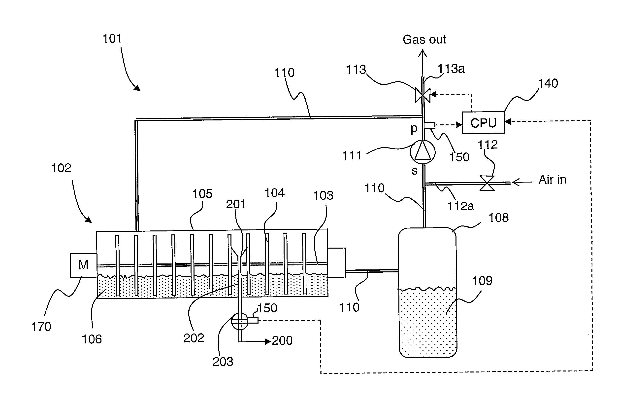
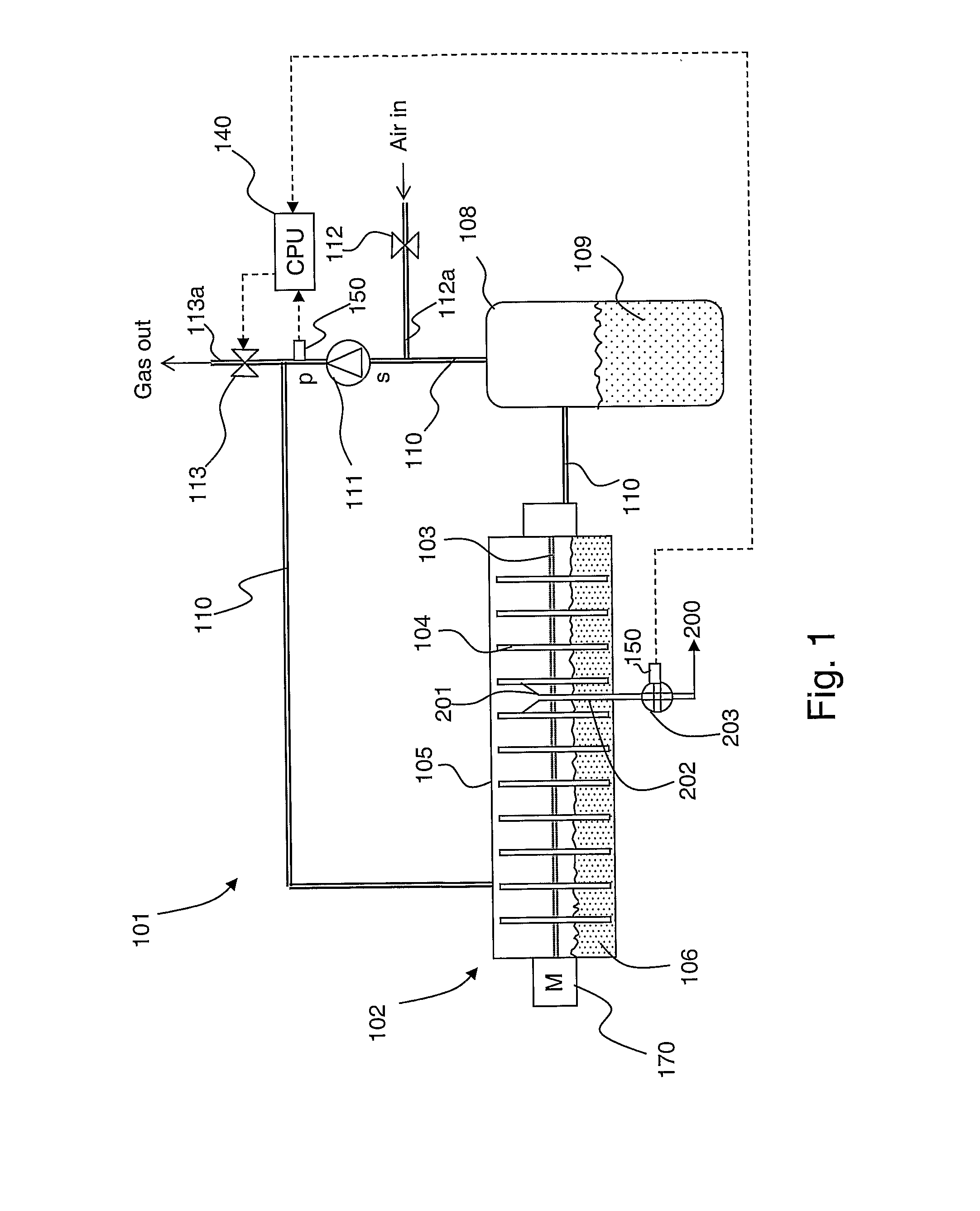
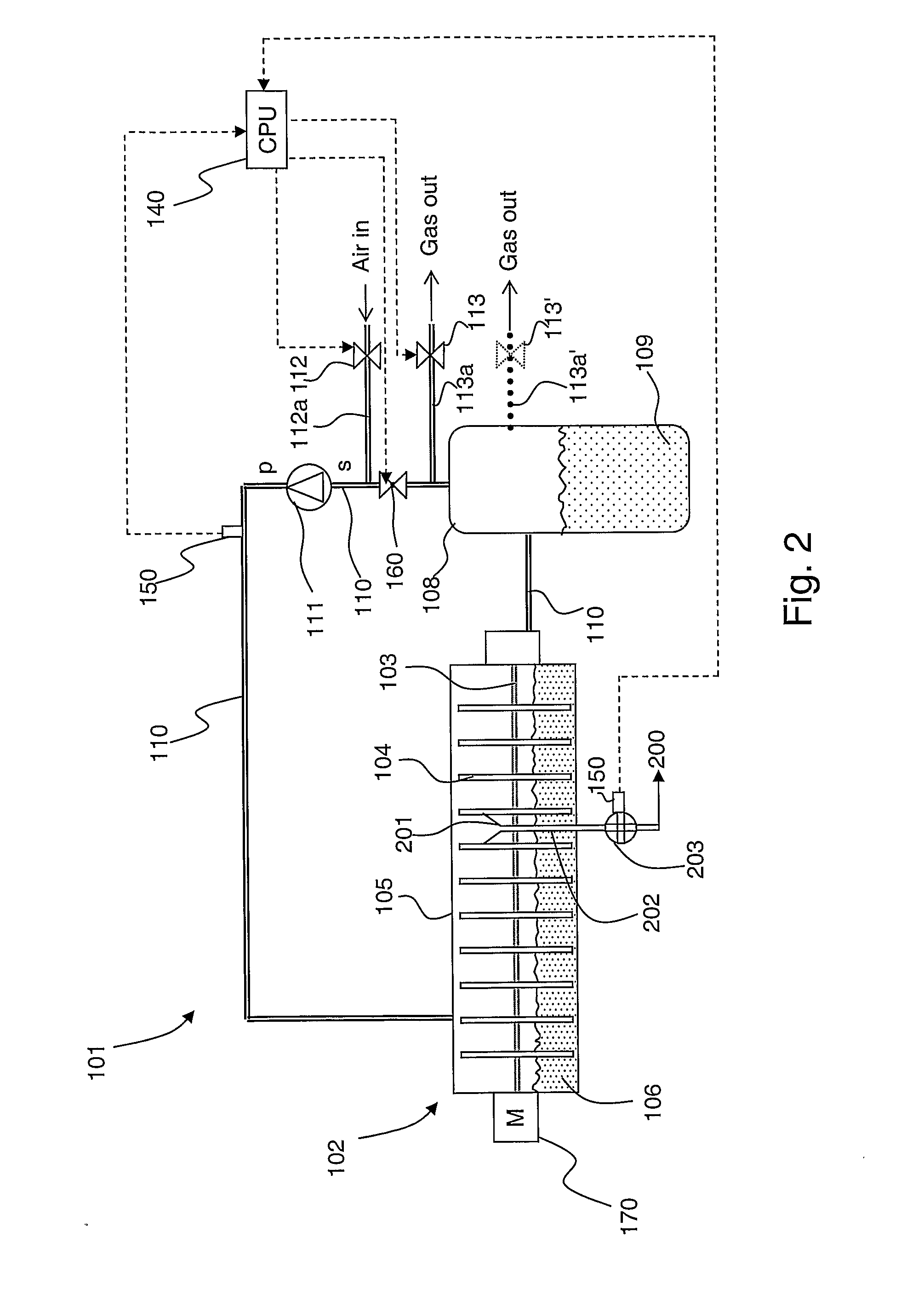
[0025] The invention is based upon the surprising insight that it is not necessary at a raised temperature and with pressurised filters to connect the lime mud side of the filter to the atmosphere in order to obtain the required amount of oxygen for the oxidation of the lime mud. It has proved to be the case that exchanging 5-20% of the recirculated gas for fresh air in the pressurised system, essentially complete oxidation of the lime mud is obtained, while at the same time an elevated temperature can be established, something that is advantageous for the oxidation of the lime mud.
[0030] The following advantages over the prior art are achieved with the invention:
[0033] Increased filtering capacity, while maintaining or reducing the area required.

Problems solved by technology

3) Oxidation of the remaining sulphide content of the lime mud.
Some of the problems / disadvantages of the currently used vacuum filters are: Considerable electrical power is consumed in creating the vacuum pressure across the filter.
The filtering capacity of the lime mud is limited, since the pressure difference across the filter is limited to atmospheric pressure.
There is a limited possibility of increasing the capacity of the filter by any other means than extension (such as a larger drum, for example).
The use of pressurised filters at the position of the final washing and dewatering stage before the lime mud kiln where vacuum filters are currently used is not normally carried out for the reasons that the oxidation of the lime mud is one of the principal aims, which requires an excess of oxygen, and that dry output from the pressurised filter is a problem.
In contrast to white liquor separation, it is desired that the lime mud be oxidised as much as possible at this position, something that is not possible using current pressurised filters that operate in closed gas systems, in which insufficient oxygen is available for oxidizing the lime mud.

Method used


Image

  • Method and Device for Washing of Lime Mud
  • Method and Device for Washing of Lime Mud
  • Method and Device for Washing of Lime Mud

Examples


Embodiment Construction

[0036] The concept “pressurised filter” will be mentioned in the following detailed description of the invention. The term “pressurised filter” is here used to denote both pressurised disc filters and pressurised drum filters.

[0037] The concepts “lime slurry” and “dewatered lime mud” will also be mentioned. The term “lime slurry” is here used to denote a slurry of lime mud that has not yet been dewatered in the filter and where the lime slurry contains lime mud+filtrate. The term “dewatered lime mud” is here used to denote lime mud that has been dewatered from filtrate by the filter and that contains only “pure” lime mud, intended for direct or indirect transport to a lime mud kiln.

[0038] Finally, the concepts “lime mud side” and “filtrate side” will be mentioned. The term “lime mud side” is here used to denote those sides of the disc or drum on which lime mud fastens during the filtration. The term “filtrate side” is here used to denote the side of the filters on which filtrate i...


PUM

PropertyMeasurementUnit
Temperatureaaaaaaaaaa
Fractionaaaaaaaaaa
Fractionaaaaaaaaaa

Abstract

The method and an arrangement are for dewatering and washing lime slurry before the dewatered lime mud is passed to a lime mud kiln. The lime slurry is dewatered in a pressurized lime mud filter of disc or drum type. The pressurized lime mud filter is pressurized through a compressor drawing on its suction side (s) gas phase from the filtrate tank and pressurizing on the pressurized side (p) of the compressor the pressure vessel on the lime mud side of the filter. A certain pre-determined amount of gas phase in the gas circulation system is vented and an equivalent pre-determined amount of fresh air is added to the recycled gas phase with the aim of maintaining the partial pressure of oxygen gas above a certain minimum level.

Description

TECHNICAL AREA [0001] The present invention relates to a method according to the introduction to claim 1 and an arrangement according to the introduction to claim 12. THE PRIOR ART [0002] During the conventional production of liquor in a soda recovery boiler, sodium carbonate (Na2CO3) and sodium sulphide (Na2S) flow out from the boiler in the form of a melt into a melt dissolver. The sodium carbonate and sodium sulphide are mixed in the melt dissolver with water to form a solution. This solution is normally known as “green liquor”. Solid contaminants are washed from the green liquor on output from the melt dissolver in a green liquor clarifier, which clarifier separates the solid contaminants from the green liquor by sedimentation. It is also possible that cleaning of the green liquor take place through the use of suitable filter equipment. The green liquor is sent after cleaning to a lime shaker in which the green liquor is mixed with burnt lime, which consists principally of calci...

Claims


Application Information

Patent Timeline
IPC IPC(8): D21C11/00B01D33/21D21CD21C11/04
CPCD21C11/0064Y02P40/40B01D33/21D21C11/0078D21C11/04
Inventor LOWNERTZ, PATRIK
Owner METABO PAPER SWEDEN
Learn More