Spindle motor having a fluid dynamic bearing system

a technology of fluid dynamic bearing and spindle motor, which is applied in the direction of sliding contact bearings, magnetic circuit rotating parts, magnetic circuit shapes/forms/construction, etc., can solve the problems of inability to produce precise surfaces required by fluid bearings in a very complex process, mechanical instability, and difficult fabrication of shafts and hubs, etc., to achieve high quality, reduce friction, and improve the effect of tilt resistan

Inactive Publication Date: 2007-09-27
MINEBEA CO LTD
View PDF22 Cites 15 Cited by
  • Summary
  • Abstract
  • Description
  • Claims
  • Application Information

AI Technical Summary

Benefits of technology

[0014]With a T-shaped shaft according to the invention, preferably made of hardened steel and including all the functional bearing surfaces on the rotor, it is possible for the connection to the hub to be realized at a diameter many times larger than that of the shaft. Since the tilt resistance of the entire rotor is dependent to a large extent on the diameter of this connecting surface, the tilt resistance can be greatly increased while retaining the same outside dimensions as in conventional designs.
[0015]Moreover, thanks to the larger connecting surface, the connection between the hub and the T-shaped shaft piece can be more surely and precisely assembled. Some variations on the embodiment even make it possible to carry out the finishing work after assembly, which goes to practically eliminate failures resulting from the connecting process.
[0016]Furthermore, important motor tolerances such as the axial play of the bearing and the perpendicularity of the axial and radial bearing surfaces, are determined only by the precision of the T-shaped shaft piece which can be realized in high quality and at low cost as a single piece in the production process and is also much easier to achieve than with the present connecting processes. In addition, deformations that are caused by the disk holding device (mainly screwed centrally in the shaft) are reduced and are located in the sensitive bearing region under the hub in contrast to a conventional design having an axial bearing.
[0017]Moreover, the diameter of the shaft

Problems solved by technology

Particularly for small-scale bearings having correspondingly small shaft diameters of sometimes less than 2 mm, the connection of the shaft and hub is thus difficult to fabricate and is mechanically unstable especially with regard to vibrations and shocks.
Due to their small joint length and small joint radius, the problem arises for small-scale bearings of the shaft being placed at a tilt in the hub, thus making the bearing incapable of carrying a load.
Here, however, the precise surfaces required by fluid bearings can only be produced in a very complex process, particularly since an annular part of the capillary seal that encloses the upper part of the shaft is formed integrally onto the hub.
As a consequence, it is difficult to work the functional surfaces of the shaft using tools, especially since the surfaces are

Method used


Image

  • Spindle motor having a fluid dynamic bearing system
  • Spindle motor having a fluid dynamic bearing system
  • Spindle motor having a fluid dynamic bearing system

Examples


Embodiment Construction

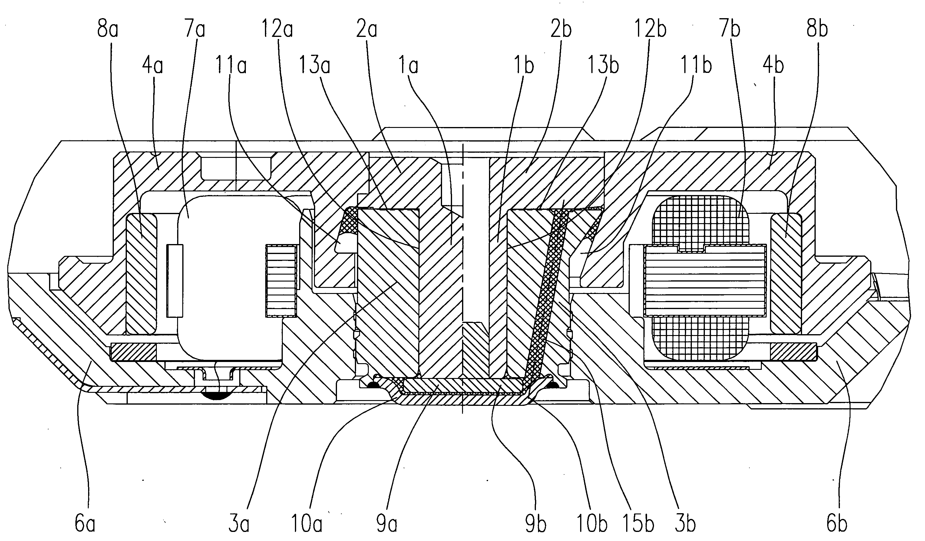
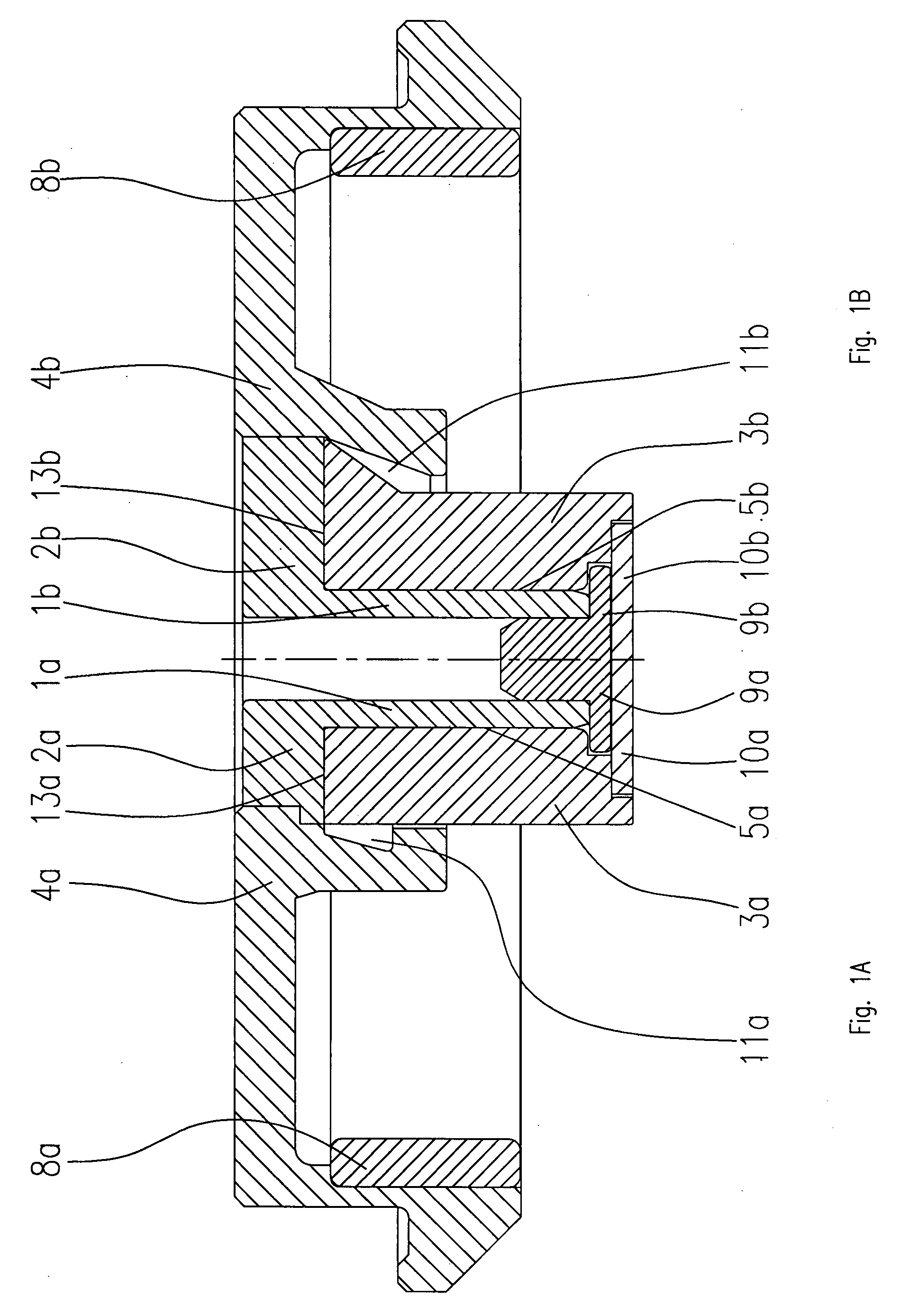
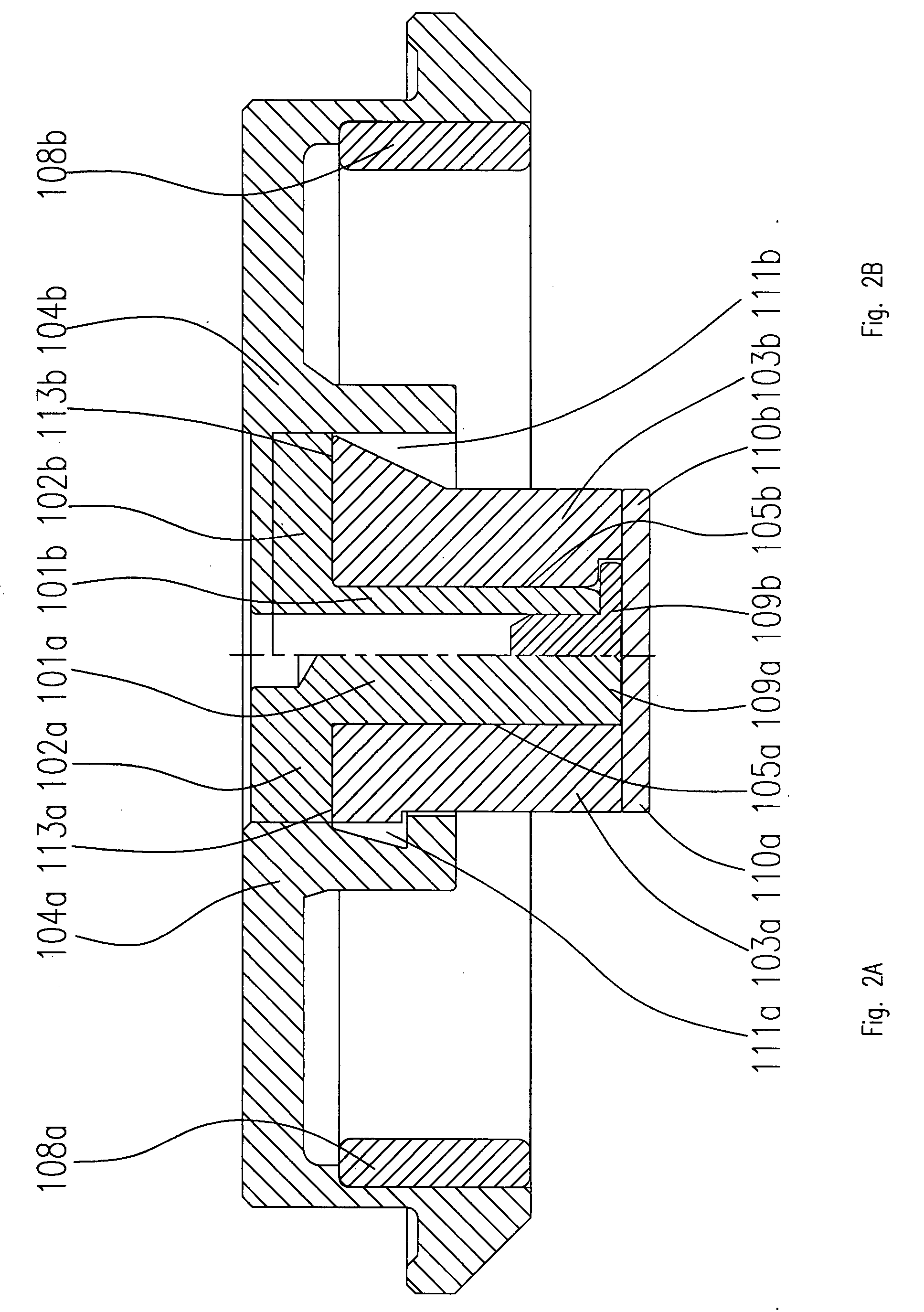
[0032]The drawings show spindle motors or parts of spindle motors respectively that are substantially made up of the same components. These spindle motors can be used, for example, for driving a hard disk drive and generally comprise a stationary baseplate 6; 306; 406 on which a stator arrangement 7; 307; 407, consisting of a stator core and windings, is disposed. A shaft 1; 101; 201; 301; 401 is rotatably accommodated in an axial, cylindrical bore in a bearing bush 3; 103; 203; 303; 403. The bearing bush 3; 103; 203; 303; 403 is connected to the baseplate 6; 306; 406. The free end of the shaft 1; 101; 201; 301; 401 carries a hub 4; 104; 204; 304; 404 that can be bell-shaped and on which one or more storage disks (not illustrated) of the hard disk drive can be disposed and fixed. An annular permanent magnet 8; 108; 208; 308; 408 having a plurality of pole pairs is disposed at the lower inner or outer edge of the hub 4; 104; 204; 304; 404, an alternating electric field being applied ...


PUM


Abstract

The invention relates to a spindle motor having a fluid dynamic bearing system, used particularly for driving the storage disks of hard disk drives, having a baseplate, a stationary bearing bush disposed in an opening in the baseplate, a shaft rotatably supported in an axial bore in the bearing bush by means of the fluid dynamic bearing system, a hub connected to the shaft, and an electromagnetic drive system. The invention is characterized in that the shaft has a flange that is fixed in an opening in the hub and whose outside diameter is significantly larger than the smallest outside diameter of the shaft.

Description

TECHNICAL FIELD OF THE INVENTION [0001]The invention relates to a spindle motor having a fluid dynamic bearing system according to the preamble of patent claim 1.PRIOR ART [0002]In spindle motors having fluid dynamic bearing systems with rotating shafts, the connection between the hub and a completely straight or slightly stepped shaft is commonly effected using a press fit. Particularly small-scale spindle motor designs (microdrives) may also use a single-piece shaft / hub component.[0003]In order to exploit as fully as possible the limited overall height that is available, one design frequently used in such small-scale form factors provides a fluid dynamic bearing system closed at the lower end having an outer, axial counterforce and only one fluid dynamic axial bearing formed between the hub and bearing bush, having a capillary seal disposed axially outwards and two radial bearings on a straight rotating shaft.[0004]These kinds of spindle motors are revealed, for example, in U.S. P...

Claims


Application Information

Patent Timeline
IPC IPC(8): H02K5/16F16C32/06
CPCF16C17/102F16C33/107F16C2370/12H02K7/085H02K1/28
Inventor DRAUTZ, FRANK
Owner MINEBEA CO LTD
Why Eureka
Try Eureka