
Calibration methods, lithographic apparatus and patterning device for such lithographic apparatus

Active Publication Date: 2007-09-27
ASML NETHERLANDS BV
View PDF4 Cites 20 Cited by
  • Summary
  • Abstract
  • Description
  • Claims
  • Application Information

AI Technical Summary

Benefits of technology

[0010] It is desirable to provide an improv

Problems solved by technology

However, the references, thus in this example the reflecting sides of the substrate table, may show imperfections, in particular may show irregularities on the surface thereof.
As the interferometers measure a length of an optical path, any unflatness of the reflecting sides will result in an error in the measurement of the position of the substrate table.
An irregularity in a flatness of the mirror (thus the reflecting side) parallel to the X axis will translate into a measurement error in the position of the substrate table in Y direction, while an unflatness at the side of the substrate table parallel to the Y axis will translate into a measurement error of the position of the substrate table in X direction.
Therefore, a position dependent error has come into existence, as a deviation of the reflecting surface may differ for each part of that surface.
Further, an error in a measurement of a rotation of the substrate table with respect to the Z axis is dependent on a position of the substrate table in Y direction, assuming that the rotation is measured by directing two or more interferometers towards a side of the substrate table which is parallel to the Y direction.
It is noted that this calibration does not provide a separate calibration for the interferometer, however provides a calibrations of the positioning system as a whole which provides for the positioning of the substrate table, the interferometer in question forming part of that positioning system.
In these configurations, each of the sensors is prone to an error which is dependent on the position of the substrate table in X direction as well as the position of the substrate table in Y direction.
To be able to calibrate the position of the substrate table in such a configuration, the calibration as described above does not provide sufficient results, as it does not take into account the multidimensional source of error which comes forward here.

Method used


Image

  • Calibration methods, lithographic apparatus and patterning device for such lithographic apparatus
  • Calibration methods, lithographic apparatus and patterning device for such lithographic apparatus
  • Calibration methods, lithographic apparatus and patterning device for such lithographic apparatus

Examples


Embodiment Construction

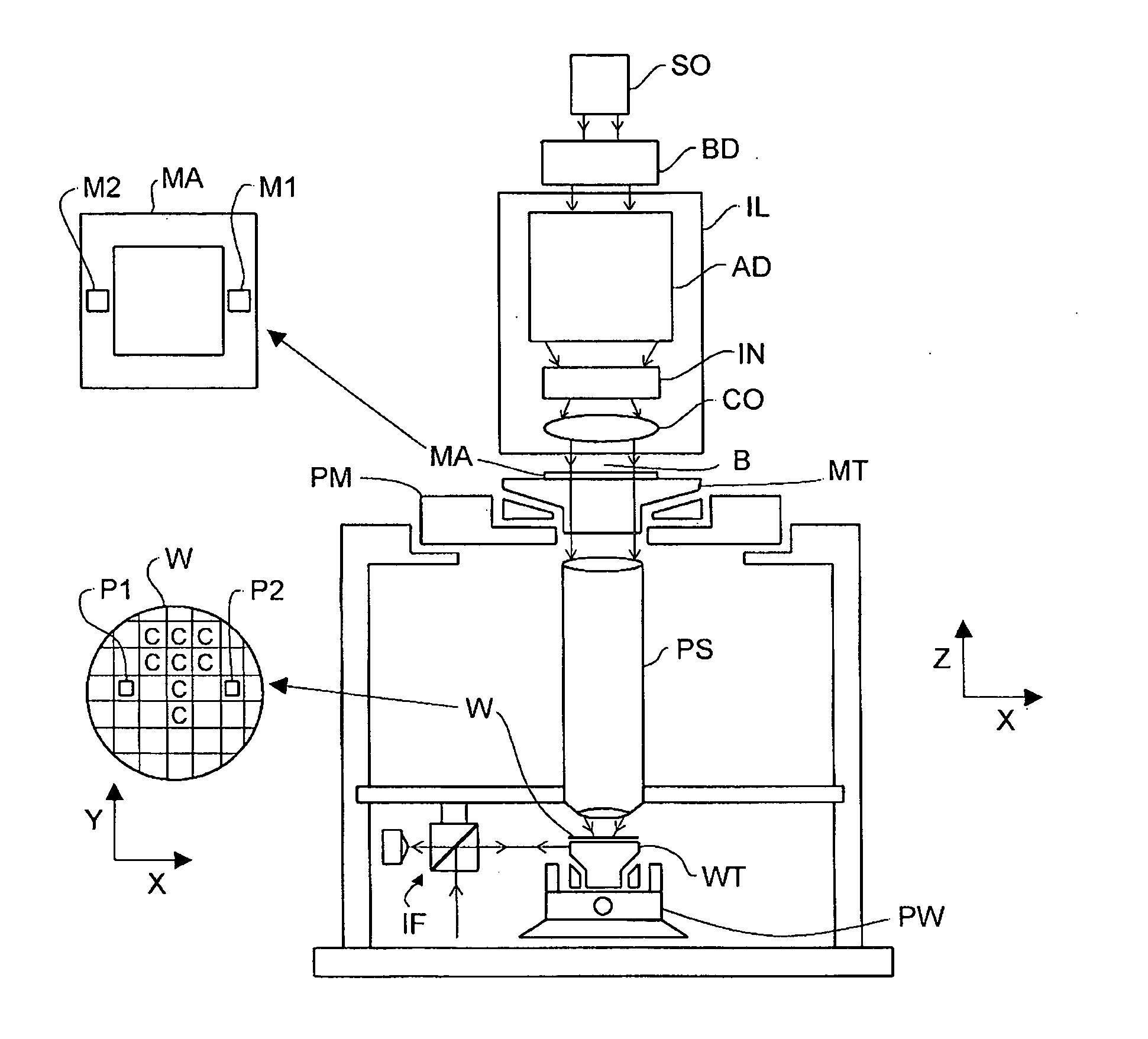
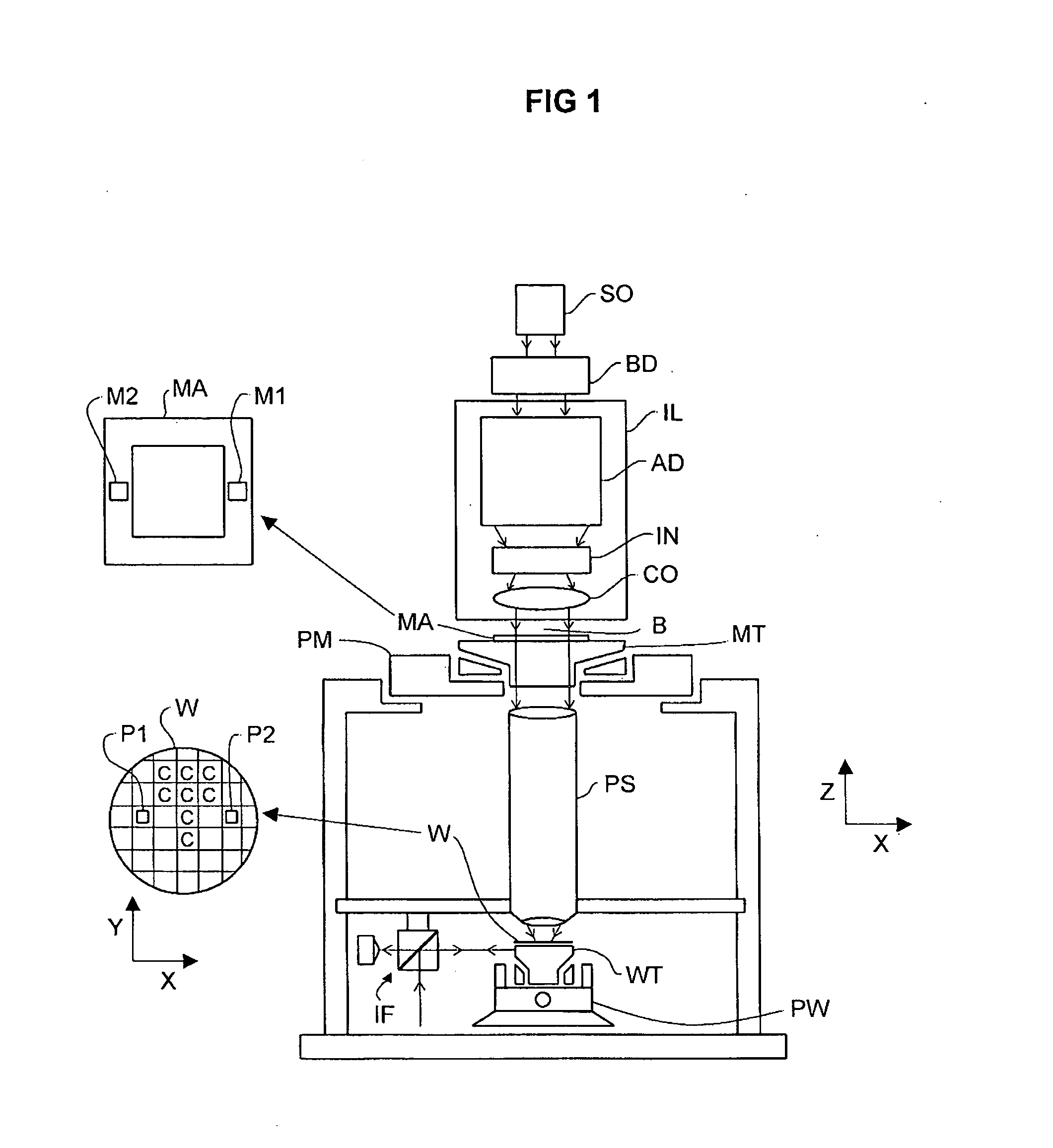
[0020]FIG. 1 schematically depicts a lithographic apparatus according to one embodiment of the invention. The apparatus includes an illumination system (illuminator) IL configured to condition a radiation beam B (e.g. UV radiation or any other suitable radiation), a mask support structure (e.g. a mask table) MT constructed to support a patterning device (e.g. a mask) MA and connected to a first positioning device PM configured to accurately position the patterning device in accordance with certain parameters. The apparatus also includes a substrate table (e.g. a wafer table) WT or “substrate support” constructed to hold a substrate (e.g. a resist-coated wafer) W and connected to a second positioning device PW configured to accurately position the substrate in accordance with certain parameters. The apparatus further includes a projection system (e.g. a refractive projection lens system) PS configured to project a pattern imparted to the radiation beam B by patterning device MA onto ...


PUM


Abstract

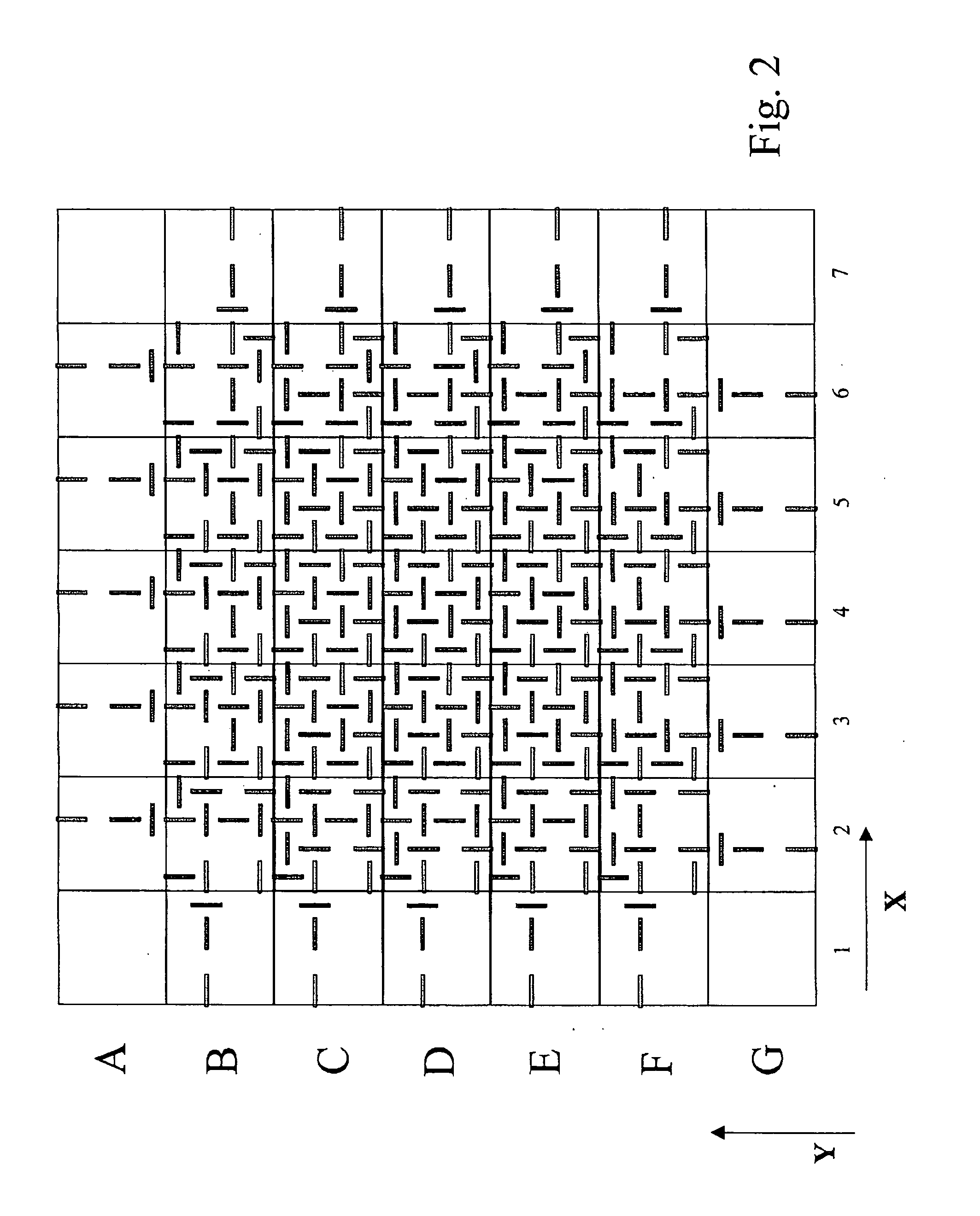
A calibration method to calibrate a substrate table position in a lithographic apparatus, the method including repeatedly irradiating a pattern onto a surface of the substrate so as to create a two dimensional arrangement of patterns on the surface of the substrate, the irradiating including displacing the substrate table between successive irradiations to irradiate the pattern onto different locations on the surface of the substrate, reading out the patterns in the two dimensions to obtain pattern read out results, deriving incremental position deviations from the read out results of neighbouring patterns in dependency on the position of the substrate table in the two dimensions, deriving from the incremental position deviations a position error of the substrate table as a function of the two dimensional position of the substrate table and calibrating the position of the substrate table using the position dependent position error.

Description

BACKGROUND [0001] 1. Field of the Invention [0002] The present invention relates to a calibration method to calibrate a substrate table position in a lithographic apparatus. Further, the invention relates to a lithographic apparatus including a control system to control a position of a substrate table, the control system being arranged to calibrate the position of the substrate table. Also, the present invention relates to a patterning device for a lithographic apparatus. [0003] 2. Description of the Related Art [0004] A lithographic apparatus is a machine that applies a desired pattern onto a substrate, usually onto a target portion of the substrate. A lithographic apparatus can be used, for example, in the manufacture of integrated circuits (ICs). In such a case, a patterning device, which is alternatively referred to as a mask or a reticle, may be used to generate a circuit pattern to be formed on an individual layer of the IC. This pattern can be transferred onto a target portio...

Claims


Application Information

Patent Timeline
IPC IPC(8): G03B27/58
CPCG03B27/58G03F7/70775G03F7/70516
Inventor KOENEN, WILLEM HERMAN GERTRUDA ANNA
Owner ASML NETHERLANDS BV
Learn More