Heat treating apparatus, heat treating method and storage medium

a heat treating apparatus and heat treatment technology, applied in microwave heating, electric/magnetic/electromagnetic heating, instruments, etc., can solve the problems of difficult to heat the wafer surface with a sufficient uniformity, the heating process pressure and the material properties of the semiconductor wafer itself are not taken into account, and the annealing process cannot be performed or not uniformly performed. , to achieve the effect of high efficiency and rapid raising or lowering

Inactive Publication Date: 2007-09-27
TOKYO ELECTRON LTD
View PDF6 Cites 48 Cited by
  • Summary
  • Abstract
  • Description
  • Claims
  • Application Information

AI Technical Summary

Benefits of technology

[0035]By irradiating the electromagnetic wave on the target object under a high vacuum level at which plasma is not generated, the temperature can be rapidly raised or lowered without be

Problems solved by technology

As a result, due to the variance in the optical characteristics, there are occasions when the annealing process can hardly be performed or cannot be uniformly performed.
However, in the above-described conventional methods,

Method used


Image

  • Heat treating apparatus, heat treating method and storage medium
  • Heat treating apparatus, heat treating method and storage medium
  • Heat treating apparatus, heat treating method and storage medium

Examples


first embodiment

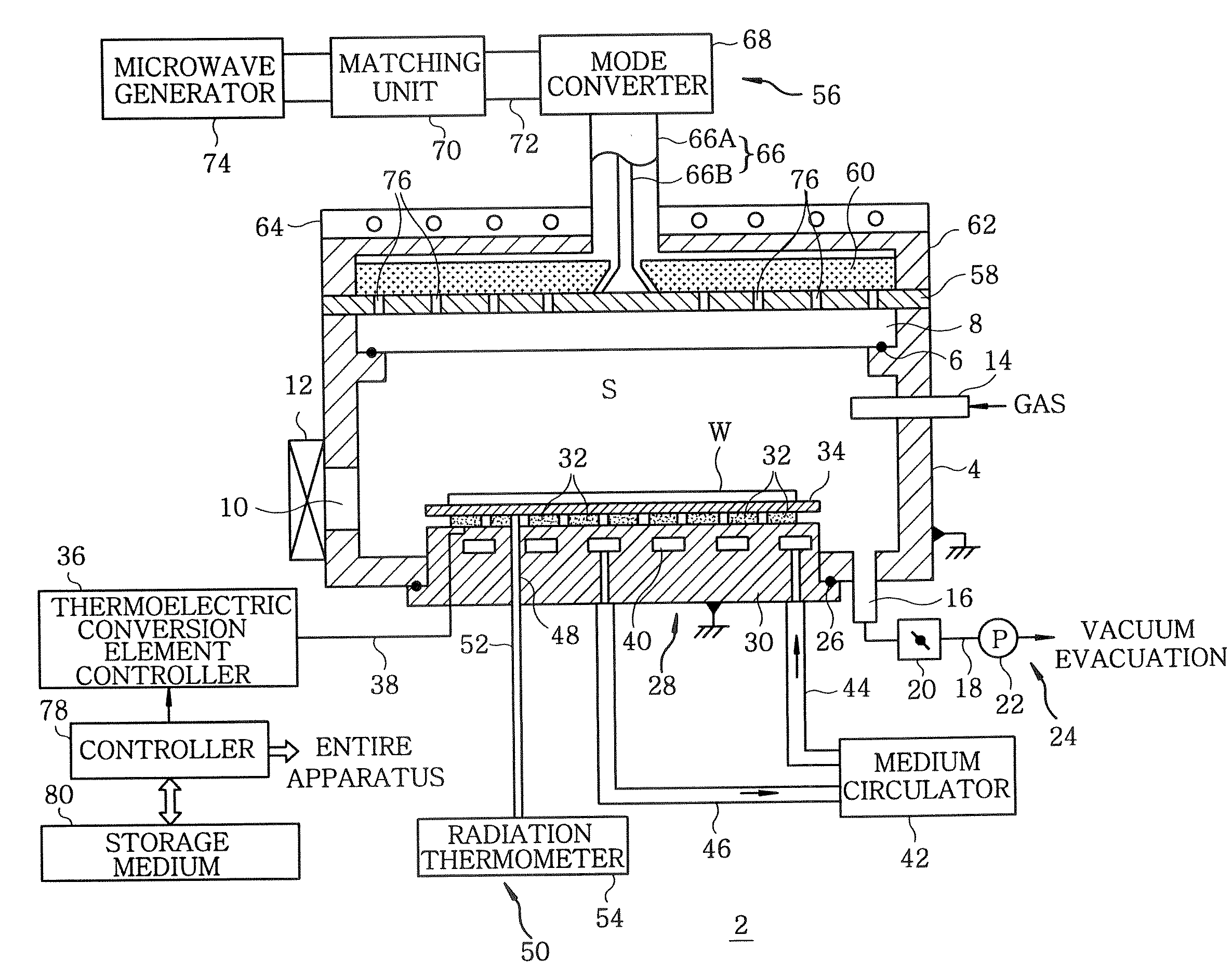
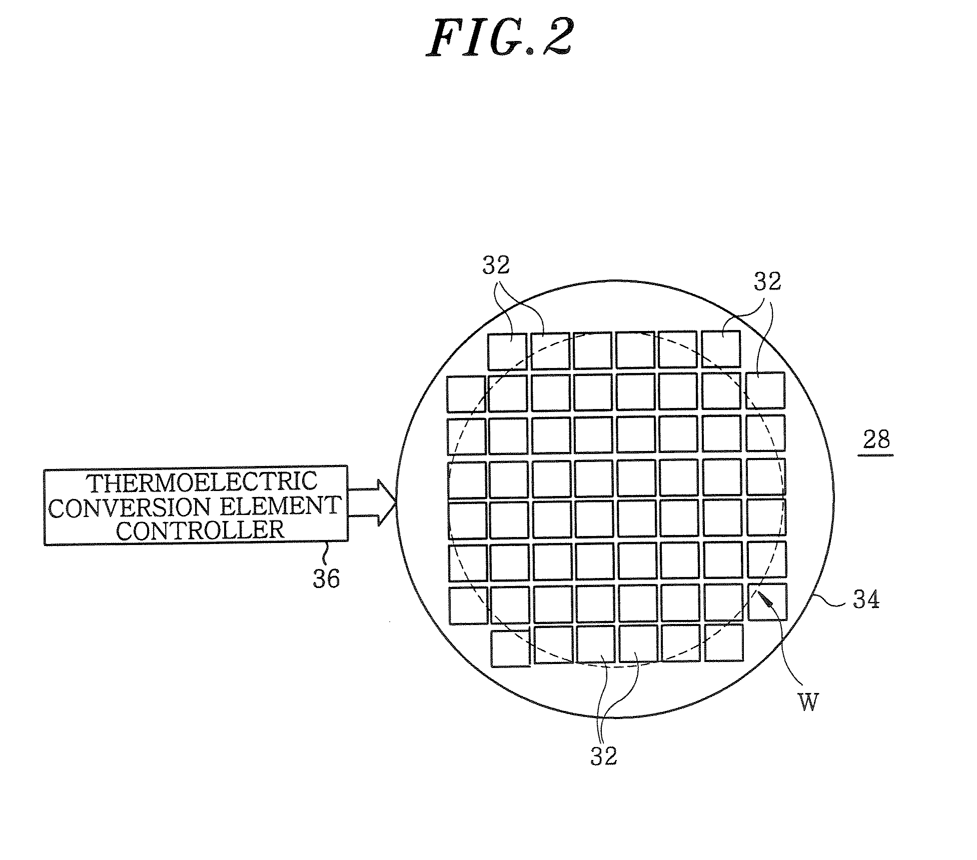
[0044]FIG. 1 provides a schematic cross sectional view of a heat treating apparatus in accordance with a first embodiment of the present invention, FIG. 2 shows a cross sectional view depicting an arrangement of thermoelectric conversion elements, and FIGS. 3A and 3B present examples of partitioning heating regions of a mounting table.

[0045]As shown in FIG. 1, a heat treating apparatus 2 of the first embodiment includes, for example, a processing chamber 4 of a housing shape made of aluminum. The processing chamber 4 is of a size capable of accommodating a semiconductor wafer having a diameter of, for example, 300 mm that is a substrate serving as a target object. The processing chamber 4 itself is grounded. A ceiling portion of the processing chamber 4 is opened. In this opening, a ceiling plate 8 for transmitting an electromagnetic wave, that will be described later, is airtightly installed by means of a sealing member 6 such as an O-ring or the like. The ceiling plate 8 is made o...

second embodiment

[0090]Hereinafter, the second embodiment of the present invention will be described. FIG. 6 provides a schematic cross sectional view of a heat treating apparatus in accordance with the second embodiment of the present invention, wherein same reference numerals are used for same parts as those shown in FIG. 1. In the following, descriptions of same parts as those described above will be omitted.

[0091]Whereas the first embodiment has been described with respect to a case of using the electromagnetic wave within a microwave band, the present embodiment will be described with respect to a case of using the electromagnetic wave within a high frequency band. Although the boundary between the high frequency wave and the microwave is usually located at about 300 MHz, the frequency of the high frequency wave should not be construed to be limited thereto. In the present embodiment, a high frequency of 13.56 MHz is used.

[0092]In FIG. 1, the planar antenna member 58 is provided with the plural...


PUM


Abstract

A heat treating apparatus, which performs a specified heat treatment on a target object, includes a processing chamber accommodating therein the target object; a mounting table for mounting thereon the target object; a vacuum exhaust system for vacuum evacuating the processing chamber; an electromagnetic wave supply unit for irradiating an electromagnetic wave onto the target object to heat the target object; and a controller for controlling the heat treating apparatus such that the electromagnetic wave is irradiated onto the target object at a high vacuum level at which plasma is not generated. Further, a heat treating method performs a specified heat treatment on a target object, wherein the target object is accommodated in a processing chamber capable of being vacuum evacuated, and the target object is heated by irradiating an electromagnetic wave thereon at a high vacuum level at which plasma is not generated in the processing chamber.

Description

FIELD OF THE INVENTION[0001]The present invention relates to a single-wafer heat treating apparatus, a heat treating method, and a storage medium for performing a specified heat treatment on a semiconductor wafer or the like by irradiating a microwave or a high frequency wave to heat the wafer.BACKGROUND OF THE INVENTION[0002]In general, in order to fabricate a desired semiconductor device, various heat treatment processes such as a film forming process, an pattern etching process, a oxidation / diffusion process, a quality modification process or annealing process are repeatedly performed on a semiconductor device. With a recent trend towards high-density, a multilayered structure and high-integration of a semiconductor device, a strict heat treating method has been required; and especially, there have been demands for an enhanced in-surface uniformity and a higher film quality of wafers in various heat treatment processes. For example, after ion-implanting impurity atoms into the ch...

Claims


Application Information

Patent Timeline
IPC IPC(8): G06F19/00H05B6/64H01L21/00H01L21/22H01L21/265H01L21/268H01L21/318H05B6/72
CPCH01L21/67115H05B6/806H01L21/68757H01L21/67248
Inventor SHIMIZU, MASAHIRO
Owner TOKYO ELECTRON LTD
Why Eureka
Try Eureka