
Automated Patient Localization in a Medical Imaging System

a technology of medical imaging and patient location, applied in the field can solve the problems of large size of medical imaging systems, and achieve the effect of increasing the throughput of the imaging center, and reducing the time necessary

Inactive Publication Date: 2007-09-27
HITACHI MEDICAL SYSTEMS AMERICA INC
View PDF11 Cites 39 Cited by
  • Summary
  • Abstract
  • Description
  • Claims
  • Application Information

AI Technical Summary

Benefits of technology

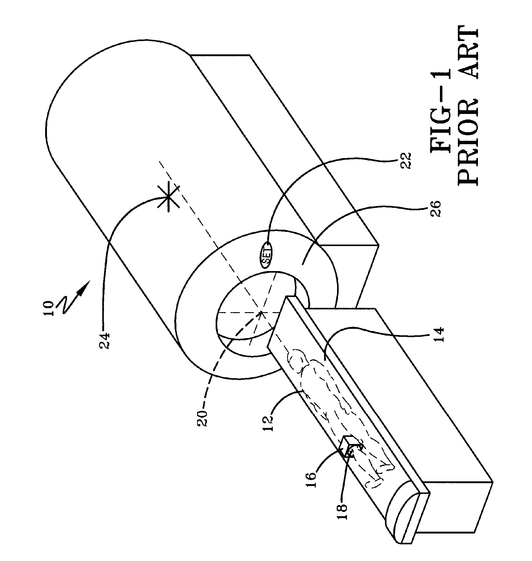
[0008] It is a further object of this invention to describe a system for patient positioning during a medical imaging procedure that operates under a process that provides for essentially continuous positioning feedback as opposed to the step process of Prior Art. After the anatomy of interest has been identified and indicated it is moved to the magnet isocenter in one step, essentially eliminating the extraneous steps currently necessary in the art of centering the anatomy of interest at a superfluous point in space that is a predetermined distance from the isocenter of the imaging system.
[0010] It is yet another object of this invention to describe a system of automated patient localization for medical imaging procedures that will decrease the human intervention necessary for positioning and preparing the patient for the scanning procedure, thus eliminating opportunities for human error and increasing the reliability of the imaging procedure.

Problems solved by technology

Some medical imaging systems are large in size and require the patient to be brought within the system for imaging.

Method used


Image

  • Automated Patient Localization in a Medical Imaging System
  • Automated Patient Localization in a Medical Imaging System
  • Automated Patient Localization in a Medical Imaging System

Examples


Embodiment Construction

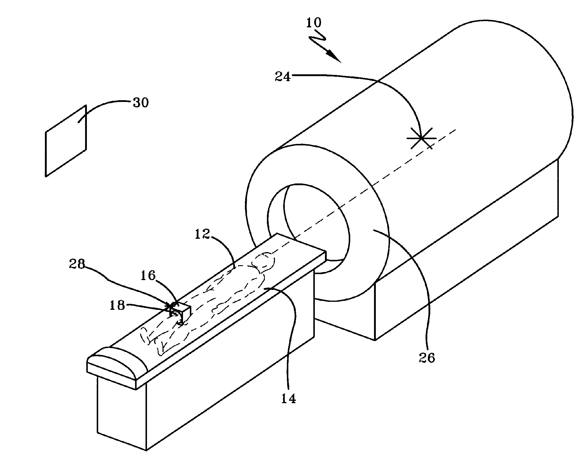
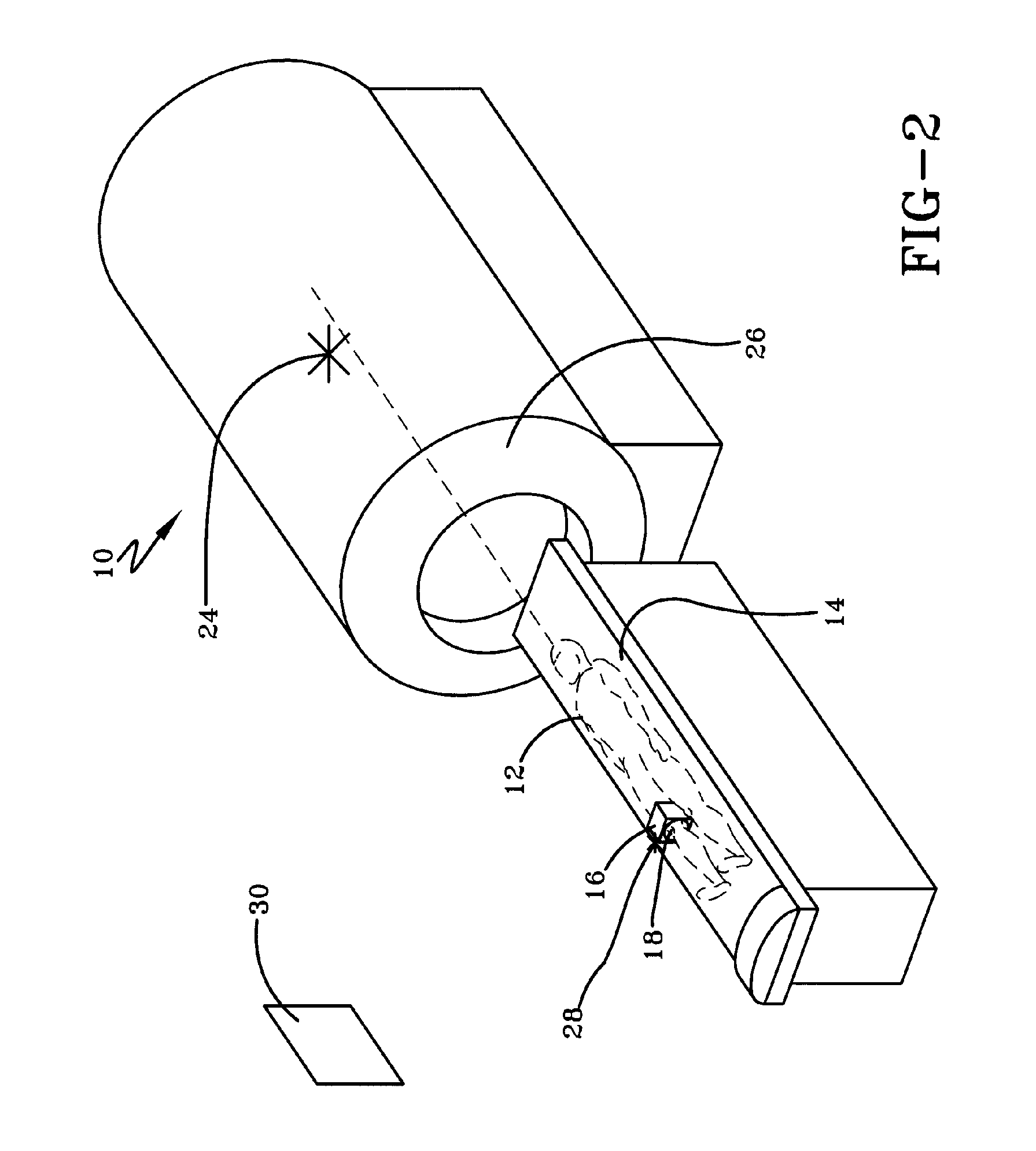
[0021] Referring now to the drawings wherein the showings are for purposes of illustrating numerous embodiments of the invention only and not for purposes of limiting the same, the figures illustrate the novel idea of a system for the automated patient localization during medical imaging techniques.

[0022] This invention is applicable to any medical imaging system that necessitates patient localization for its proper function, such as magnetic resonance imaging (MRI) systems, positron emission tomography (PET) systems, optical tomography, single photon emission computed tomography (SPECT), and computerized aided tomography (CAT) systems. FIG. 2 illustrates a horizontal field magnetic resonance imaging (MRI) system incorporating a preferred embodiment of the current invention for automated patient positioning. This invention is applicable to any MRI system, and is not limited by the field orientation, field strength, or architecture of the system. The invention applies to, but is not...


PUM


Abstract

Described herein is a process for patient localization within a medical imaging system, having a first and second signal means for identifying patient position. The patient is manually positioned on a patient table at an initial position outside the system. A first signal means is manually positioned adjacent an area of interest on the patient in the initial position and the first signal means communicates that initial patient position to a detection means. The second signal means communicates a desired final patient position location to the detection means. The detection means either essentially continuously monitors and compares said initial and subsequent positions to the final position, or calculates the distance between the initial position and the final position and causes the patient to move from the initial position to the final position when the positions are not essentially the same.

Description

TECHNICAL FIELD [0001] The invention relates generally to medical imaging systems, and more specifically to the automated alignment of patients within such systems. BACKGROUND OF THE INVENTION [0002] Medical imaging is the process of using a specialized system to create an image of a person's internal organs, tissues, and other structures and characteristics that cannot commonly be seen with the human eye. Some medical imaging systems are large in size and require the patient to be brought within the system for imaging. For these types of systems, commonly a patient is positioned on a movable table that can advance into the medical imaging system. The patient is positioned at a specific reference point within the system, and imaging by the system occurs. [0003] Magnetic resonance imaging (MRI) is a commonly used medical imaging technology. Within a magnetic resonance imaging (MRI) system a patient table, commonly called the patient couch, extends into the bore of the magnet, and exi...

Claims


Application Information

Patent Timeline
IPC IPC(8): A61B5/05
CPCA61B5/0555G06Q50/24G06Q50/22G16H40/63G16H30/20A61B5/055A61B5/704
Inventor STECKNER, MICHAEL
Owner HITACHI MEDICAL SYSTEMS AMERICA INC
Learn More