Orthopedic Implants Coated with Pyrolytic Carbon

a technology of pyrolytic carbon and orthopedic implants, which is applied in the direction of prosthesis, impression caps, shoulder joints, etc., can solve the problems of excessive wear of the cartilage with which the implants come in contact, and achieve the effects of reducing the risk of fractur

Inactive Publication Date: 2007-09-27
SANTILLI ALBERT N +1
View PDF21 Cites 22 Cited by
  • Summary
  • Abstract
  • Description
  • Claims
  • Application Information

AI Technical Summary

Benefits of technology

[0009] In response to the foregoing concerns, the present invention provides a new and improved orthopedic implant. The orthopedic implant according to the present invention comprises a metal substrate coated on an articulating surface with pyrolytic carbon or an alloy of pyrolytic carbon. The invention can be used with virtually any type of orthopedic implant. In one illustrative form of the present invention, a resurfacing shoulder implant comprises a head that is designed to fit over at least a portion of the proximal end of the humerus bone. The implant according to the invention further comprises a stem, preferably fenestrated, for insertion into an opening in the humerus bone. The head is comprised of a cap having a porous coating. Typically, the cap is made of a metal such as titanium or stainless steel, or alloys thereof. The coating over the cap comprises pyrolytic carbon or an alloy thereof, preferably applied by vapor deposition.
[0010] The orthopedic implants of the present invention enjoy significant advantages that existing orthopedic implants do not. The pyrolytic coating on the articulating surface makes the implants of the present invention resistant to friction and wear, resistant to blood clotting, resistant to adverse reactions when implanted into a human body, and resistant to damage of surrounding cartilage. The use of a metallic substrate provides a strong, biocompatible material for the body of the implant. The substrate also has excellent adhesion characteristics for pyrolytic carbon. The foregoing features and advantages will be apparent from the accompanying drawings and the description that follow.

Problems solved by technology

These implants usually are not susceptible to wear, but instead cause the cartilage with which they come in contact to wear excessively.

Method used


Image

  • Orthopedic Implants Coated with Pyrolytic Carbon
  • Orthopedic Implants Coated with Pyrolytic Carbon
  • Orthopedic Implants Coated with Pyrolytic Carbon

Examples


Embodiment Construction

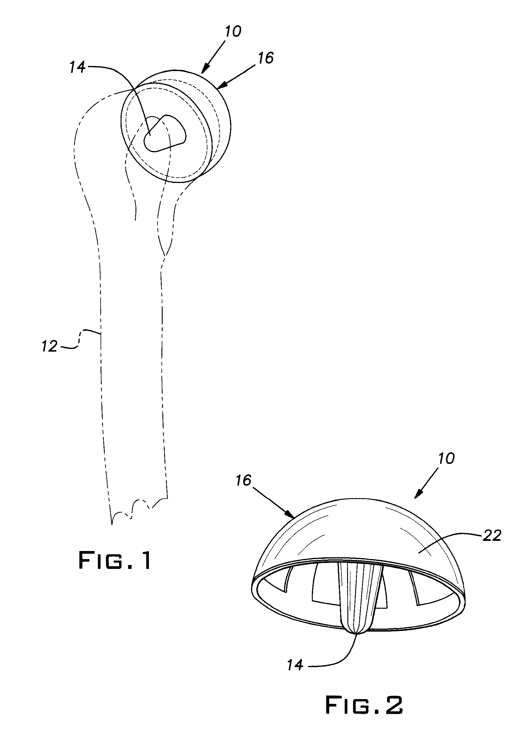
[0016] Referring to FIG. 1, an implant 10 according to the present invention is shown. The implant 10 is intended to be implanted into the head of a humerus bone 12. Unlike a complete shoulder implant, the implant 10 is a resurfacing implant that is designed to cover or cap only the top portion of the humerus bone 12.

[0017] Although the invention is described herein in the context of a resurfacing shoulder implant 10, it is to be understood that the description of the invention in such an application is for illustrative purposes only. The present invention is applicable to virtually all types of orthopedic implants, including radial head implants, basal thumb implants, spinal implants, etc.

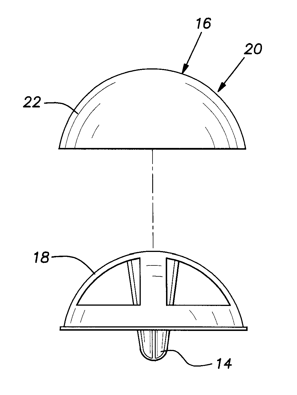
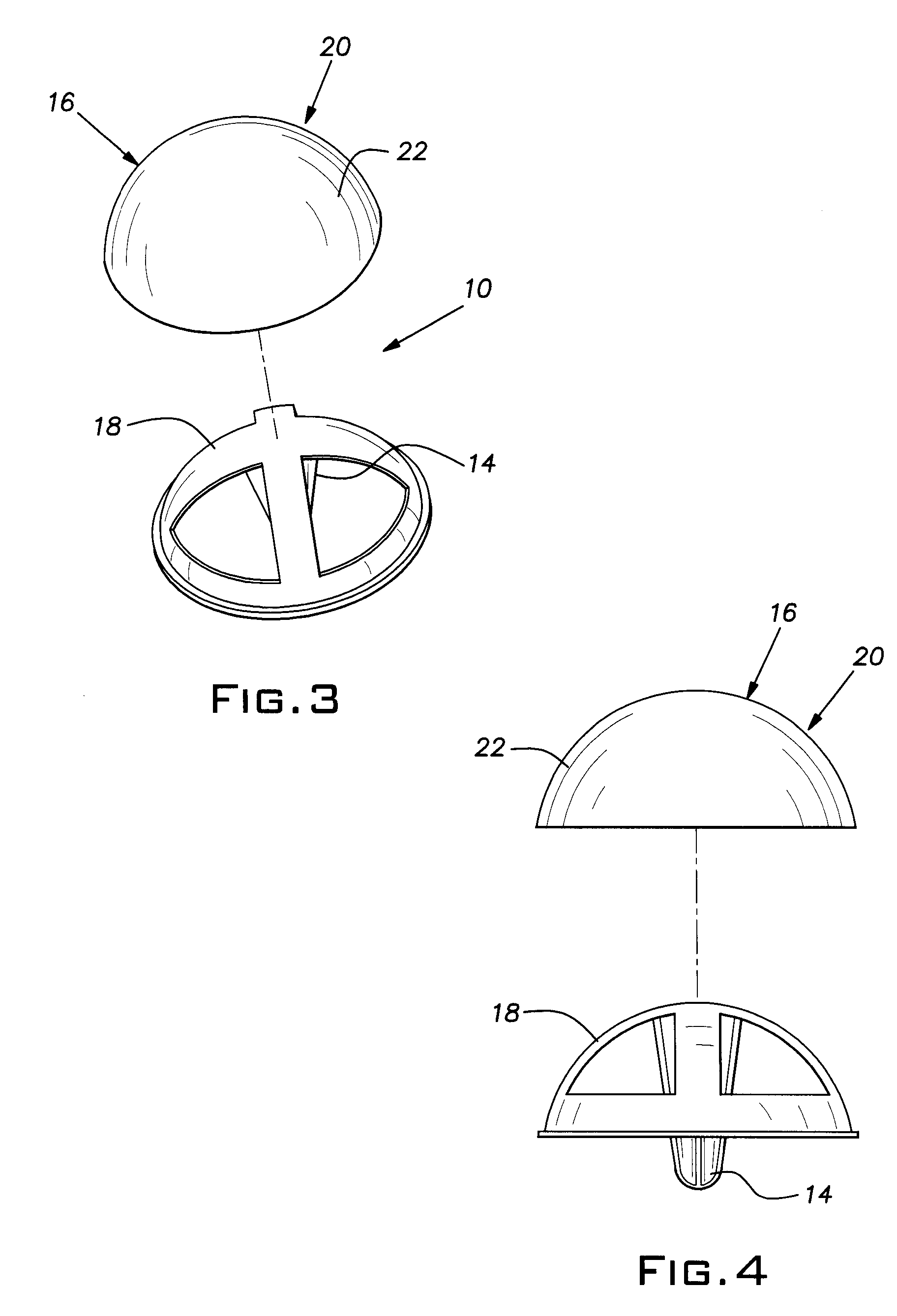
[0018] The implant 10 comprises a dome or head 16 and a stem 14. FIGS. 2 through 4 illustrate, via multiple perspectives, various parts of the implant 10. FIG. 2 is a perspective view of one embodiment of the implant 10, FIG. 3 is an exploded perspective view of the implant 10 shown in FIG. 2, a...


PUM

PropertyMeasurementUnit
thicknessaaaaaaaaaa
thicknessaaaaaaaaaa
thicknessaaaaaaaaaa

Abstract

An orthopedic implant having a metal substrate with an articulating surface includes a coating for the articulating surface made of pyrolytic carbon. Typically, the substrate is made of a metal such as titanium or stainless steel, or alloys thereof. The pyrolytic carbon coating preferably is applied by vapor deposition.

Description

1. REFERENCE TO RELATED APPLICATIONS [0001] The present application is a continuation-in-part of U.S. application Ser. No. 11 / 608,454, filed Dec. 8, 2006, which claims priority from U.S. provisional application No. 60 / 749,131, filed Dec. 9, 2005.BACKGROUND OF THE INVENTION [0002] 2. Field of the Invention [0003] The present invention relates generally to orthopedic implants and, more particularly, to orthopedic implants having a coating of pyrolytic carbon thereon. [0004] 3. Description of the Prior Art [0005] Orthopedic implants currently are made of many different types of materials. Some implants are made of ultra-high molecular weight polyethylene, while others are made of biocompatible materials such as titanium, titanium alloys, surgical alloys, stainless steels, ceramics, and cobalt chrome. It is desirable for an orthopedic implant to be made of material that has properties similar to bone, that is resistant to wear from frictional forces, and that is durable and strong. It a...

Claims


Application Information

Patent Timeline
Patent Type & Authority Applications(United States)
IPC IPC(8): A61F2/36A61F2/28B05D5/00
CPCA61F2/30767C23C30/00A61F2/44A61F2002/30299A61F2002/30604A61F2002/30616A61F2002/30878A61F2002/30934A61F2002/30981A61F2002/3827A61F2002/4007A61F2230/0093A61F2310/00017A61F2310/00023A61F2310/00029A61F2310/00574A61L27/422A61F2/4003A61F2/3094A61L27/04A61L27/303B05D5/00
Inventor SANTILLI, ALBERT N.SEITZ, WILLIAM H. JR.
Owner SANTILLI ALBERT N
Why Eureka
Try Eureka