Manufacturing method of caulking-assembled part

a manufacturing method and assembly technology, applied in the field of high-strength caulking technique, can solve the problems of limiting the cost reduction, increasing the manufacturing cost for forming the specific shape, and increasing the material cost and process cost, so as to achieve sufficient caulking strength and reduce the cost. , the effect of reducing the cos

Active Publication Date: 2007-10-04
JAPAN
View PDF1 Cites 9 Cited by
  • Summary
  • Abstract
  • Description
  • Claims
  • Application Information

AI Technical Summary

Benefits of technology

[0010] Then, in view of the above conditions, it is an object of the present invention to provide a caulked assembly which can be manufactured at low cost easily without providing the flange part at the middle part of the columnar body such as the shaft body and producing the complicated specific shape, and maintain sufficient caulking strength even in the thin plate body, and the manufacturing method thereof.
[0011] It is another object of the present invention to provide a caulked assembly which can perform the caulking of the magnesium or magnesium alloy material having worse processability at low cost easily without requiring the rotation or the like of the punch and deforming the shaft, and maintain sufficient caulking strength even in the thin plate body made of the magnesium or magnesium alloy, and a manufacturing method thereof.
[0012] Also, it is another object of the present invention to provide an assembly which can sufficiently correspond to the reduction in the thickness of the resin molded plate, realize the firm junction, improve the caulked accuracy such as the perpendicular degree and provide the shape of the caulked member comparatively freely, be assembled at low cost in a short time, and correspond as the fixing method for the precision components, a manufacturing method thereof, and a manufacturing apparatus thereof.

Problems solved by technology

Thereby, it is necessary to cut a shaft material which is about 50% thicker than a shaft diameter required for product use to produce a flange shape, which increases a material cost and a process cost.
The manufacture cost is also increased for forming the specific shape, which limits the cost reduction.
However, the worse processability thereof causes extremely difficult caulking of a shaft with, particularly, a thin plate.
This method has had problems such as large-scale devices required for increased manufacture cost and low flexibility of the design because of indispensable shaft deformation.
However, the press fitting could not secure sufficient strength when the thickness of the resin molded plate is reduced.
The adhesion method using the solvent could not fundamentally attain the perpendicular degree easily, had inconvenient freedom of the shape, required long junction time to reduce the manufacturing efficiency, and was hardly introduced as a fixing method for precision components.
However, such a method to press the second member on the first member inevitably causes reduction in the perpendicular degree of the second member.
Since the method fixes the first member using the resin turned to the flat surface side of the second member, and the obtained structure requires a sufficient turing amount, firm combination cannot be maintained if the melted resin is blocked in the concave portion of the processing horn, and the management is troublesome.
Furthermore, the first member must have a thickness for embeding the flat surface of the second member, and cannot be applied to the reduction in the thickness of the plate.
The processing horn having a specific shape is required for every kind of the second member, and unfortunately, the cost is increased.

Method used


Image

  • Manufacturing method of caulking-assembled part
  • Manufacturing method of caulking-assembled part
  • Manufacturing method of caulking-assembled part

Examples


examples

[0292] Next, the result of strength test of each of caulked assemblies of examples 1 to 6 assembled by the manufacturing method of the present invention will be described.

[0293] Examples 1 to 6 are respectively prepared by assembling the end part of a columnar body (shaft body) made of an aluminium alloy with a plate body made of an aluminium alloy by caulking in the method of the first embodiment. The outer diameters of the columnar bodies and the plate thicknesses of the plate bodies are shown in Table 1.

TABLE 1Outer diameterPlate thickness(mm) of columnar body(mm) of plate bodyExample 16.151.5Example 22.5Example 311.01.5Example 42.5Example 515.01.5Example 62.5

[0294] In these examples 1 to 6, push-in strength, falling strength and rotating strength (only examples 3 to 6) were respectively tested. Referring to the push-in strength, as shown in FIG. 40(a), a plate body 2 is placed on a base 6 in which an escaping hole 60 is formed. The plate body is fixed to the base 6 at a posit...


PUM

PropertyMeasurementUnit
forceaaaaaaaaaa
distancesaaaaaaaaaa
distancesaaaaaaaaaa

Abstract

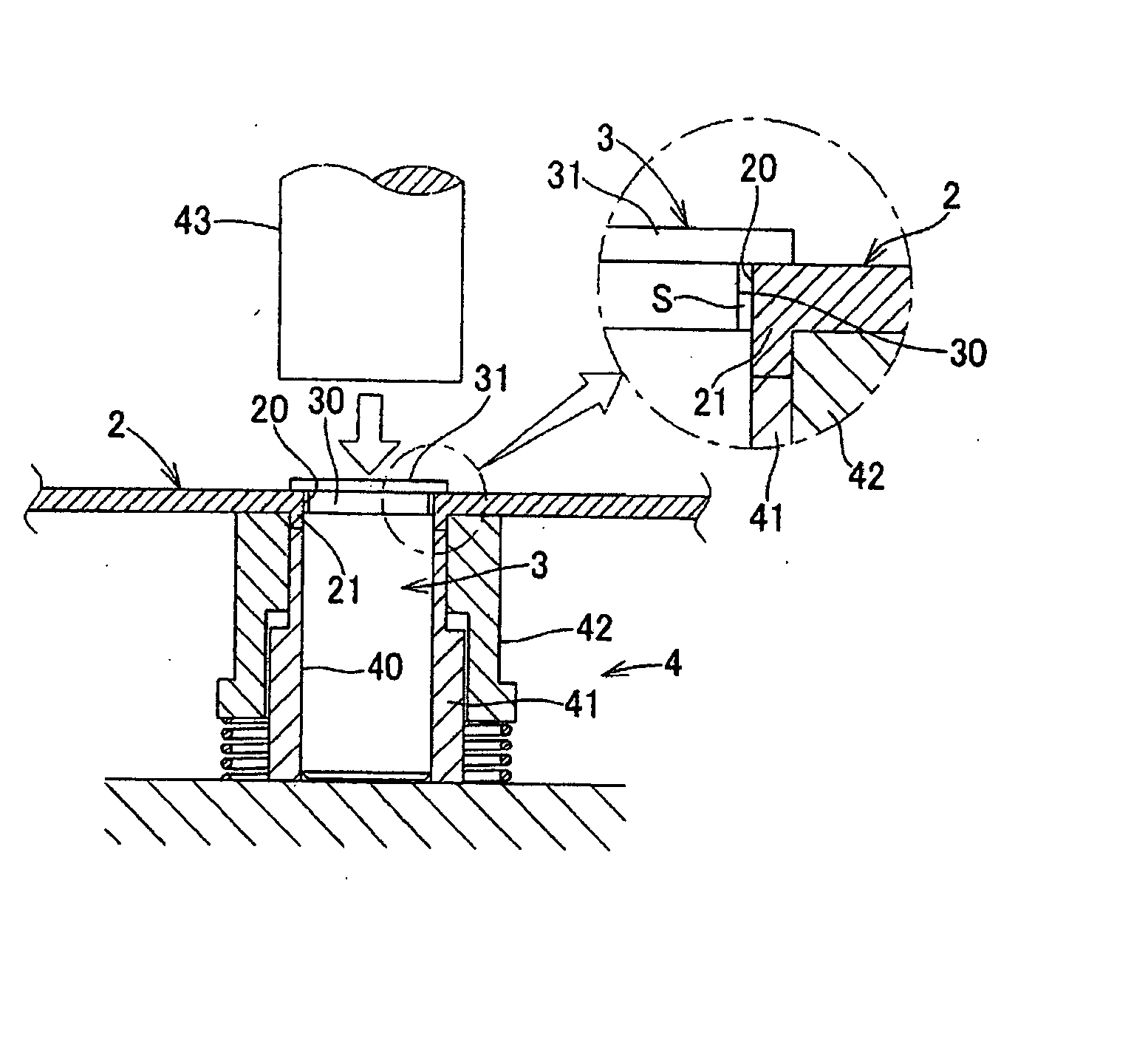
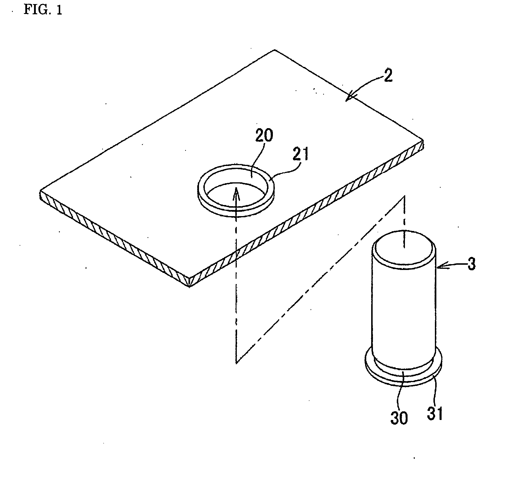
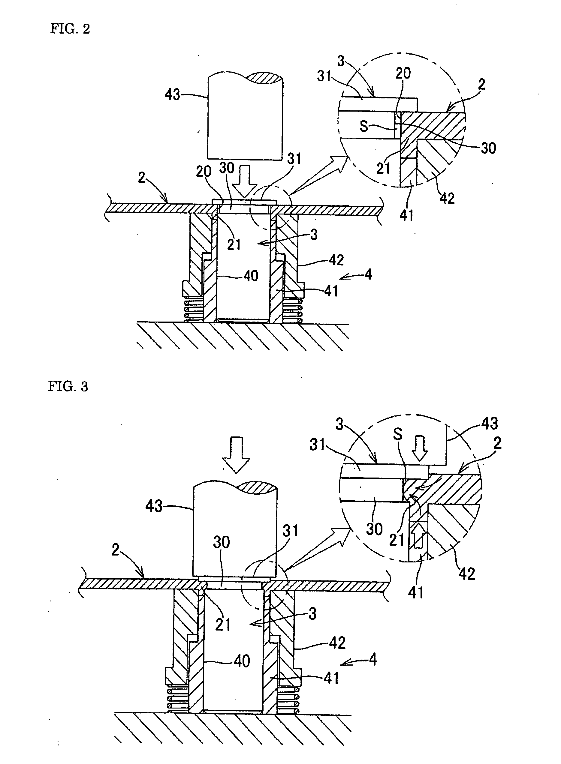
The present invention provides a caulked assembly to be manufactured at low cost, and maintain sufficient caulking strength, and the manufacturing method and apparatus thereof. The manufacturing method comprises steps of forming a mounting hole for inserting and assembling a columnar body in a metal plate body, and forming a thick part along an inner circumferential edge of a mounting hole; forming a circumferential groove with a predetermined depth at an assembled position of a outer circumferential surface of the columnar body inserted into the mounting hole; inserting the columnar body into the mounting hole to set to the assembled position where the thick part is opposed to the circumferential groove; and caulking for compressively pressing the thick part from an axial direction of the columnar body to plastically deform the thick part in a center direction of the mounting hole to bite the thick part into the circumferential groove.

Description

BACKGROUNG OF THE INVENTION [0001] 1. Field of the Invention [0002] The present invention relates to a high-strength caulking technique capable of firmly fixing a hollow or solid columnar body to a metal plate body. Particularly, the present invention relates to a high-strength caulking technique capable of firmly fixing a hollow or solid columnar body to a plate body made of magnesium or a magnesium alloy. Also, the present invention relates to a caulking technique of a resin molded body made of a thermoplastic resin with a hollow or solid columnar body made of a material having a higher melting point than that of the thermoplastic resin. [0003] 2. Description of the Background Art [0004] Caulking of this kind of a plate body with a columnar body has been conventionally performed as follows. In Patent Reference 1, a flange part is formed at the middle part of a shaft body side as shaft caulking, and a circular hole is punched in the side of a plate body which is a press component a...

Claims


Application Information

Patent Timeline
Patent Type & Authority Applications(United States)
IPC IPC(8): B23P11/00
CPCB21K23/04B21K25/00Y10T29/49908F16B17/006Y10T29/49915B23P11/00
Inventor WATANABE, HIROYUKIKAWASAKI, HISANORIWATANABE, HIDEMITSU
Owner JAPAN
Why Eureka
Try Eureka