Sheet hole punching apparatus and sheet hole punching method

a hole punching apparatus and hole punching technology, applied in the direction of electrographic process, manufacturing tools, instruments, etc., can solve the problems of excessive load on the drive motor, mechanical failure, and high load on the hole punching member

Inactive Publication Date: 2007-10-04
SEIKO CORP
View PDF7 Cites 34 Cited by
  • Summary
  • Abstract
  • Description
  • Claims
  • Application Information

AI Technical Summary

Benefits of technology

[0020]A sliding member (sliding cam) that advances and retreats with a predetermined stroke, a drive motor that moves the sliding member, punch members that are moved in the thrusting direction by the reciprocating action of the sliding m

Problems solved by technology

If the volume of paper cutting debris increases, there is the possibility that the cuttings can find their way into the device through the blade bearing holes.
Particularly, when operating the punch and paper cutting debris accumulates into a pile directly below the punch members, a higher load than what is required is applied to the hole-punching members and an excessive load is applied to the drive motor.
These loads can lead to mechanical failure.
Also, if paper cutting debris on the die gets inside the device, there is the problem of incorrect

Method used


Image

  • Sheet hole punching apparatus and sheet hole punching method
  • Sheet hole punching apparatus and sheet hole punching method
  • Sheet hole punching apparatus and sheet hole punching method

Examples


first embodiment

of the Hole-punching Device

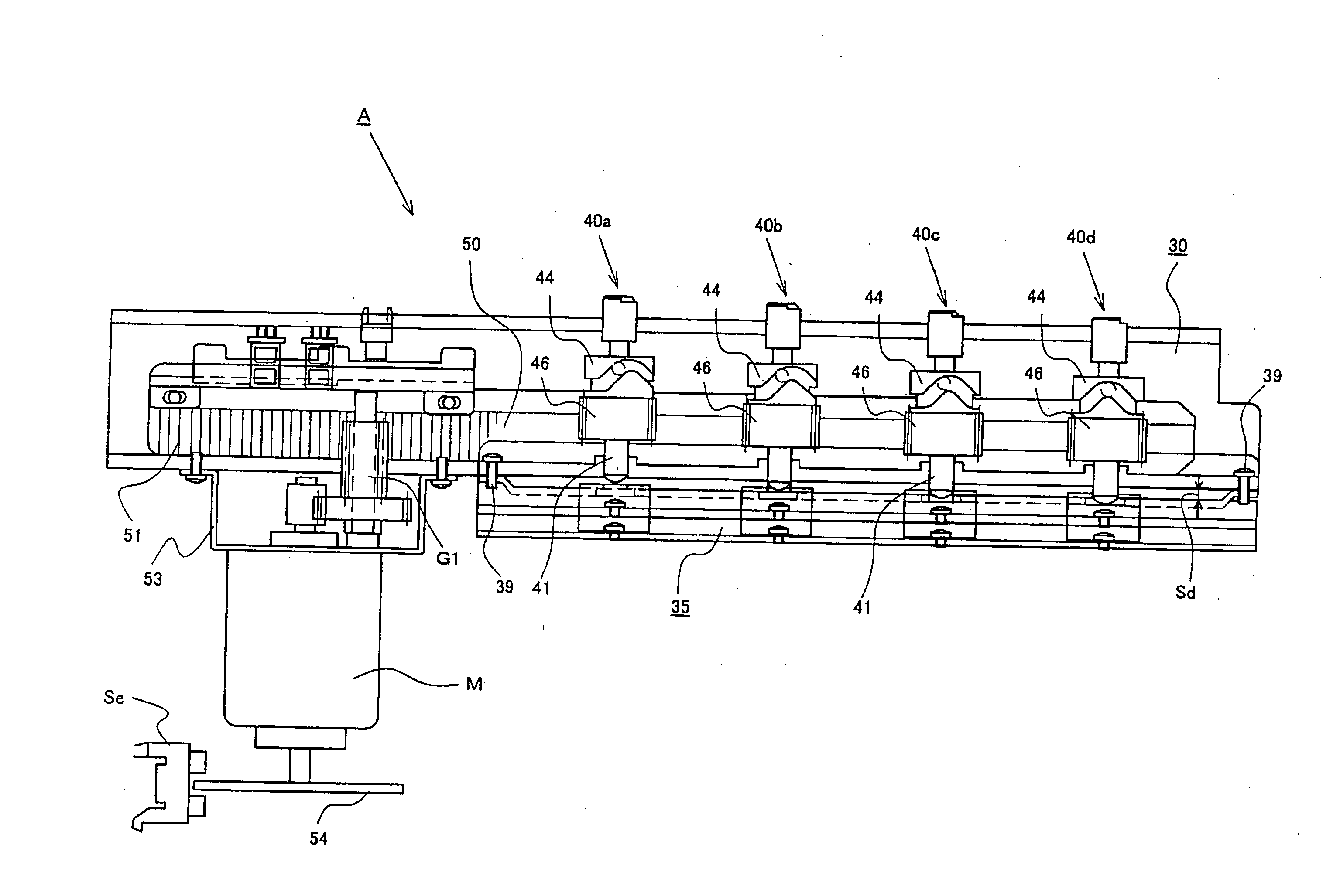
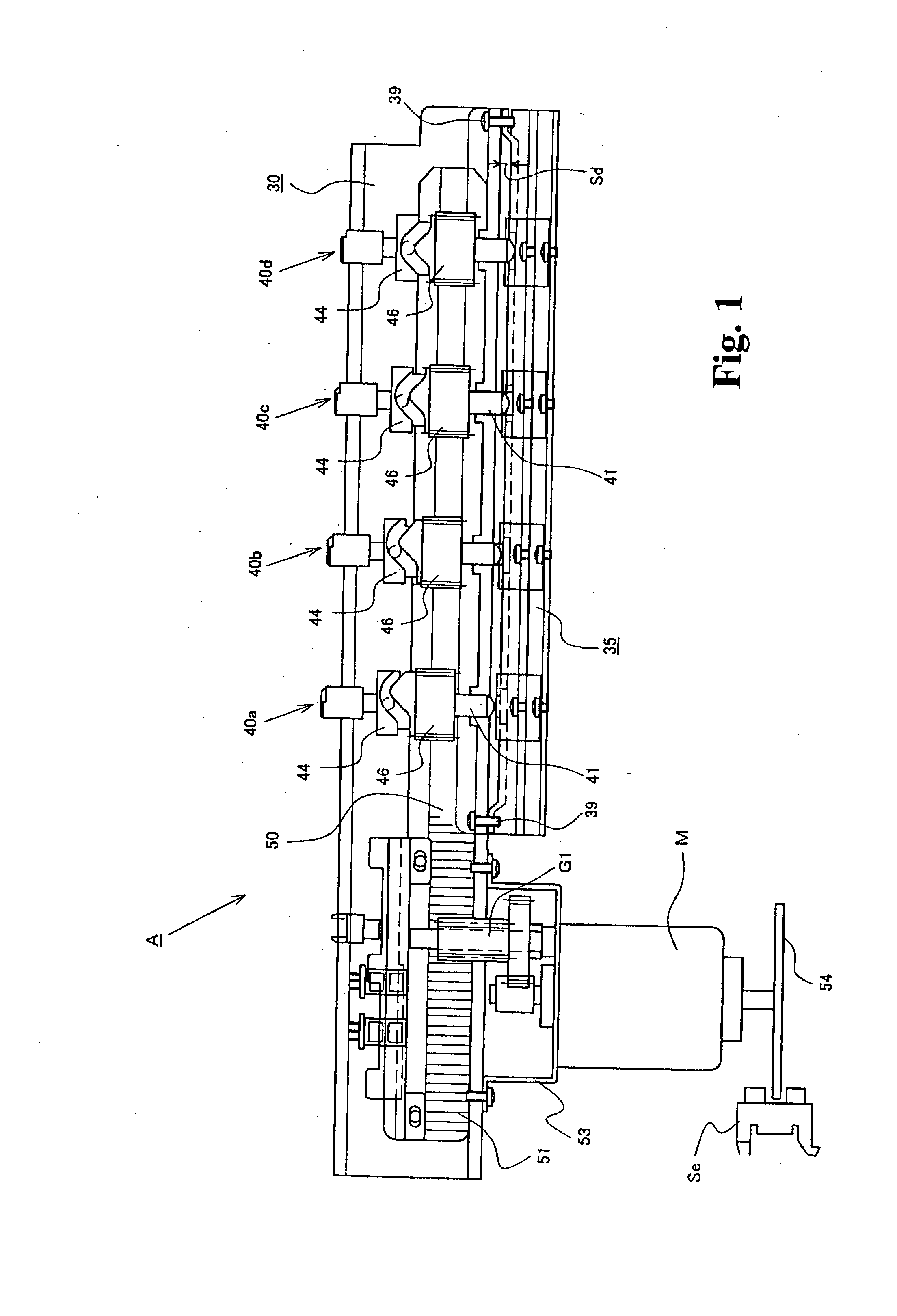
[0055]The following will explain the hole-punching device A shown in FIG. 1. The hole-punching device A is composed of a base frame (hereinafter referred to as the upper frame) 30 having a length dimension that corresponds to the sheet S that is to be punched with holes; a lower frame (hereinafter referred to as the die plate) 35 forming a space Sd with the upper frame 30 for setting the sheet S; punch members 40 installed in the upper frame 30; and blade bearing holes 38 disposed in the lower frame 35. The punch members 40 are formed into ordinary cylindrical shapes; a hole-punching blade 41 is disposed on each of the leading ends of the punch members 40. These punch members 40 are disposed at predetermined standard (standard for filing holes) position on the upper frame 30. There can be two, three or even four of these punch members 40. Shown in the drawing are a first punch member 40a; a second punch member 40b; a third punch member 40c; and a fourth pu...

second embodiment

of the Hole-punching Device

[0086]A different embodiment of the device shown in FIG. 1 will now be explained with reference to FIGS. 9(a) and 9(b) and 10(a), 10(b) and 10(c). As shown in FIG. 10(a), a cylindrical cam 66 is fastened to base frame 30. A lead pin 65 that engages a cam groove 67 of the cylindrical cam 66 is disposed at the punch member side. Configurations that are the same as those shown in FIG. 1 have the same symbols. Explanations of those members will be omitted.

[0087]The upper frame 30 and the lower frame 35 have the same structure as those shown in FIG. 1; both are integrally joined to form a unit. A drive motor M and drive shaft 60 that is connected to this drive motor M are disposed on the upper frame 30, as shown in FIG. 10(a). The same upper guide 31 and lower guide 32 as described above are equipped on the upper frame 30. The punch members 40 are slidably supported on the guide holes 31a and 32a of the upper and lower guides 31 and 32. The punch members 40 are...

third embodiment

of the Hole-punching Device

[0094]The following will now explain a third embodiment shown in FIG. 11 that differs from the first and second embodiments. The configuration of the punch members 40 is the same as that described in relation to the second embodiment, so the same symbols will be used but an explanation thereof will be omitted. FIG. 11 shows each punch member 40 moving upward and downward with a predetermined stroke by the reciprocating movement of a sliding cam 82, instead of the drive cam (eccentric cam) 61. A V-shaped groove cam 83 is formed in the sliding cam 82 connected to the drive motor M, not shown. This V-shaped groove cam 83 is equipped with an oblique cam surface 83a inclined to a predetermined angle in the hole-punching direction. A cam follower pin 83p that engages the V-shaped groove cam 83 is implanted in a cap member 84 mated to the punch member 40. The cap member 84 is pivotably supported to rotate on the top end of the punch member 40. Other configuration...


PUM

PropertyMeasurementUnit
Thicknessaaaaaaaaaa
Forceaaaaaaaaaa
Speedaaaaaaaaaa

Abstract

A cylindrical punch member equipped at the leading end thereof with a hole-punching blade is movably supported on a base frame in a hole-punching direction. A drive means is equipped that applies thrusting force to the punch member; a cam follower member disposed between the base frame and punch member engages a cam means disposed at either the base frame or punch member. An oblique cam surface inclined at a predetermined angle with regard to a hole-punching direction is equipped in cam means to give rotational drive force around an axis of rotation to the punch member that is moved in the hole-punching direction by the drive means. This configuration causes each of a plurality of cylindrical punch members to rotate around their axes of rotation when moved in a hole-punching direction by drive means thereby punching a hole in a sheet with a reduced shear force; the centrifugal force of that punch member rotation causing paper cutting debris to be scattered evenly under the punch member.

Description

BACKGROUND OF THE INVENTION[0001]1. Field of the Invention[0002]The present invention relates to a hole punching method, a hole punching device and a finishing apparatus, which are used in conjunction with image forming apparatuses, that punch holes in sheets conveyed out from an image forming apparatus such as a copier, printing machine or printer and the like.[0003]2. Description of the Related Arts[0004]Such a variety of hole-punching devices have been well known, as performing punch-holes in sheets by manually pushing hole-punching members downward into a plurality of sheets, and automatic hole-punching devices that punch holes in sheets conveyed out of a printing machine or copies as office devices for punching holes in paper. The former is widely known as a device for penetrating sheets by disposing cylindrically shaped punching members that shuttles up and down, on a frame member that sandwiches sheets. By pressing an operating lever downward, these cylindrically shaped hole-...

Claims


Application Information

Patent Timeline
IPC IPC(8): B23D25/02B26D1/56
CPCB26D5/16B26D7/1818B26F1/04Y10T408/858B26F1/16G03G15/6582Y10T408/6779B26F1/14Y10T83/0515Y10T83/4711Y10T83/8828Y10T83/8843Y10T83/943Y10T83/944
Inventor BABA, KENJI
Owner SEIKO CORP
Why Eureka
Try Eureka