Methods for removing photoresist

Inactive Publication Date: 2007-10-04
SEMITOOL INC
View PDF14 Cites 58 Cited by
  • Summary
  • Abstract
  • Description
  • Claims
  • Application Information

AI Technical Summary

Benefits of technology

[0005] Sulfuric acid and hydrogen peroxide have been used for many years in efforts to strip or remove photoresist, with varying degrees of success. It has now been discovered however, that the sequence and parame

Problems solved by technology

It has now been discovered however, that the sequence and par

Method used


Image

  • Methods for removing photoresist
  • Methods for removing photoresist
  • Methods for removing photoresist

Examples


Embodiment Construction

A. Methods

[0009] 1. Sulfuric Acid and Sulfur Trioxide

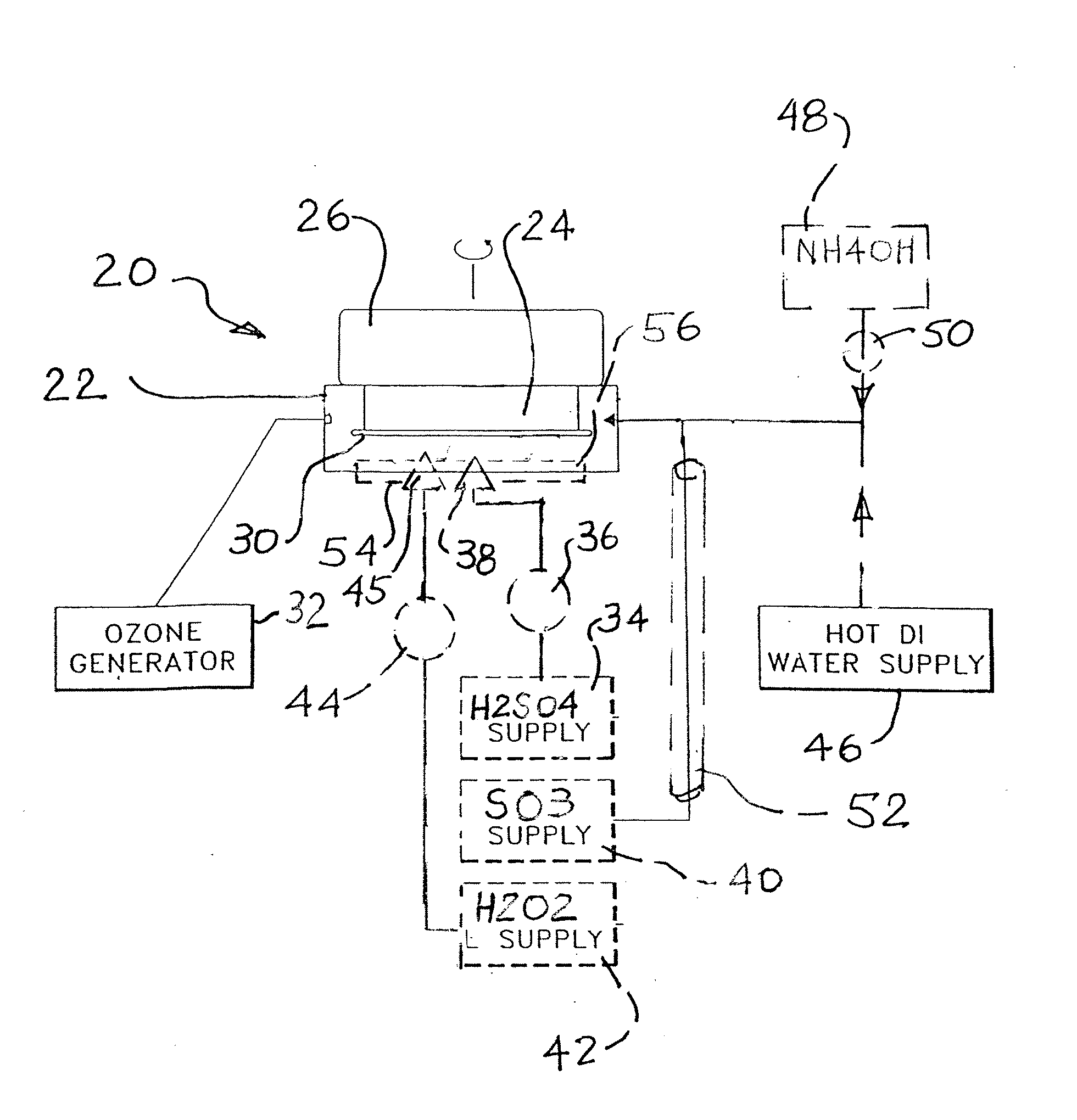
[0010] Sulfuric acid (H2SO4), and particularly fuming sulfuric (sulfuric acid in conjunction with sulfur trioxide (SO3)) may be used for stripping photoresist. Fuming sulfuric acid is commonly called oleum and is sulfuric acid with a percentage of sulfur trioxide dissolved in solution. Fuming sulfuric acid may be made by reacting water and SO3, dissolving SO3 in H2SO4 or by applying SO3 already dissolved in H2SO4. If SO3 is used, it may be delivered into an enclosed process chamber either by bubbling a carrier gas through the SO3 or by delivering a pressurized stream of SO3 to the process chamber. The flow rate may typically be in the range of 0.25-10 liters / minute.

[0011] The photoresist on the wafer surface may be initially wetted with water or steam. Spinning the wafer to thin the water film may optionally be used. Even a microscopic wetting of the wafer surface may be advantageous. Water may be supplied prior to or concurrent...


PUM

PropertyMeasurementUnit
Temperatureaaaaaaaaaa
Timeaaaaaaaaaa

Abstract

In a method for removing an organic film such as photoresist from a wafer, the wafer is placed into a chamber. A liquid including an acid, such as sulfuric acid is applied to the surface of the wafer. Sulfur trioxide is supplied into the chamber. Alternatively, fuming sulfuric acid may be used. The wafer may optionally be spinning in the chamber. The liquid forms a liquid layer on the surface of the workpiece. The chemical reaction of the acid and the SO3 removes the organic film. Further improved results may be achieved in removing many organic films by heating the wafer, or the liquid, or both. Providing ozone gas into the chamber may also be helpful in some applications. In a related method, an organic film is removed from a wafer by applying an acid film or layer on to the surface of the wafer. The acid, is heated. An oxidizer is then delivered to the heated acid film. The combined action of the acid and the oxidizer removes the organic film, typically without leaving any residues. The acid may be sulfuric acid and the oxidizer may be hydrogen peroxide.

Description

PRIORITY CLAIM FOR THE UNITED STATES [0001] This Application claims priority to U.S. Provisional Patent Application Nos. 60 / 744,254 filed Apr. 4, 2006 and 60 / 862,009, both incorporated herein by reference. Thus novel methods and apparatus have been shown and described. Various changes and substitutions may of course be made without departing from the spirit and scope of the invention. The invention, therefore, should not be limited, except by the following claims and their equivalents. Where not inconsistent with the context, singular terms include the plural, and vice versa. Similarly, use of the term “or” here may mean “or” or “and / or”.BACKGROUND [0002] Semiconductor wafer patterns are typically created by applying a photoresist to the wafer surface. Exposing a pattern on the wafer alters the chemical bonding of the photoresist, which allows certain regions to be removed using a developer while other regions become relatively inert to the developer. Photoresist may be either posit...

Claims


Application Information

Patent Timeline
IPC IPC(8): C23G1/00C23G1/02B08B7/00B08B3/00
CPCG03F7/423
Inventor BERGMAN, ERIC J.
Owner SEMITOOL INC
Why Eureka
Try Eureka