Power converter

Inactive Publication Date: 2007-10-04
HITACHI LTD
View PDF1 Cites 16 Cited by
  • Summary
  • Abstract
  • Description
  • Claims
  • Application Information

AI Technical Summary

Benefits of technology

[0018]According to the present invention, the difference in current between the upper arm and the lower arm is read in, and thus current can be detected even when only the upper arm is set to 100% ON-state or only the lower arm is set to 100% ON-state. As a result, a current sensor which is high in precision, compact in size and low in loss can b

Problems solved by technology

The conventional techniques as described above have not paid sufficient attention to these points.
In the above conventional techniques, the current sensor having the insulating core is expensive in price, and also requires a structure such as a bus bar penetrating through the sensor or the like as a passage for primary current.
Therefore, the number of parts is increased, and the size of the structure is increased, so that the cost further rises up.
According

Method used


Image

  • Power converter
  • Power converter
  • Power converter

Examples


first embodiment

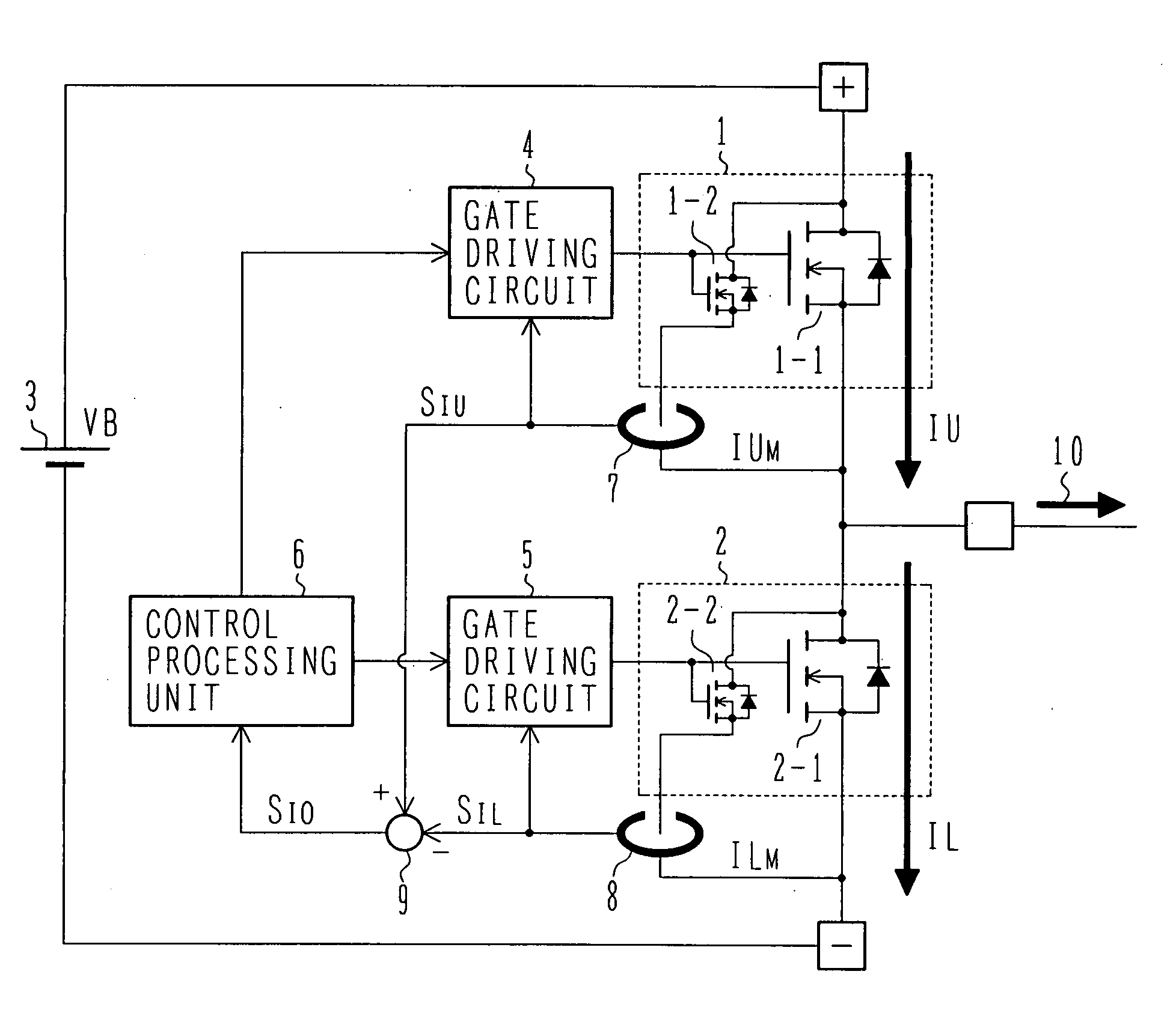
[0024]FIG. 1 shows a first embodiment in which the present invention is applied to a switching circuit used in a field chopper circuit or an electric motor control device as disclosed in JP-A-2004-48863 described above.

[0025]In the first embodiment, a switching device 1 serving as an upper arm and a switching device 2 serving as a lower arm are connected in series between a positive terminal and a negative terminal to which a DC voltage VB is applied from a DC power source 3, and current IU and IL flowing through the respective elements respectively are switched, whereby output current IO is supplied from an output terminal 0 to a load (not shown) such as a motor or the like.

[0026]Each of the switching devices 1, 2 is equipped with a gate driving circuit 4, 5, and subjected to switching control under the control of a control operating unit 6. At this time, the output current IO of an accurate value cannot be supplied to a load such as a motor or the like at any time unless the contr...

second embodiment

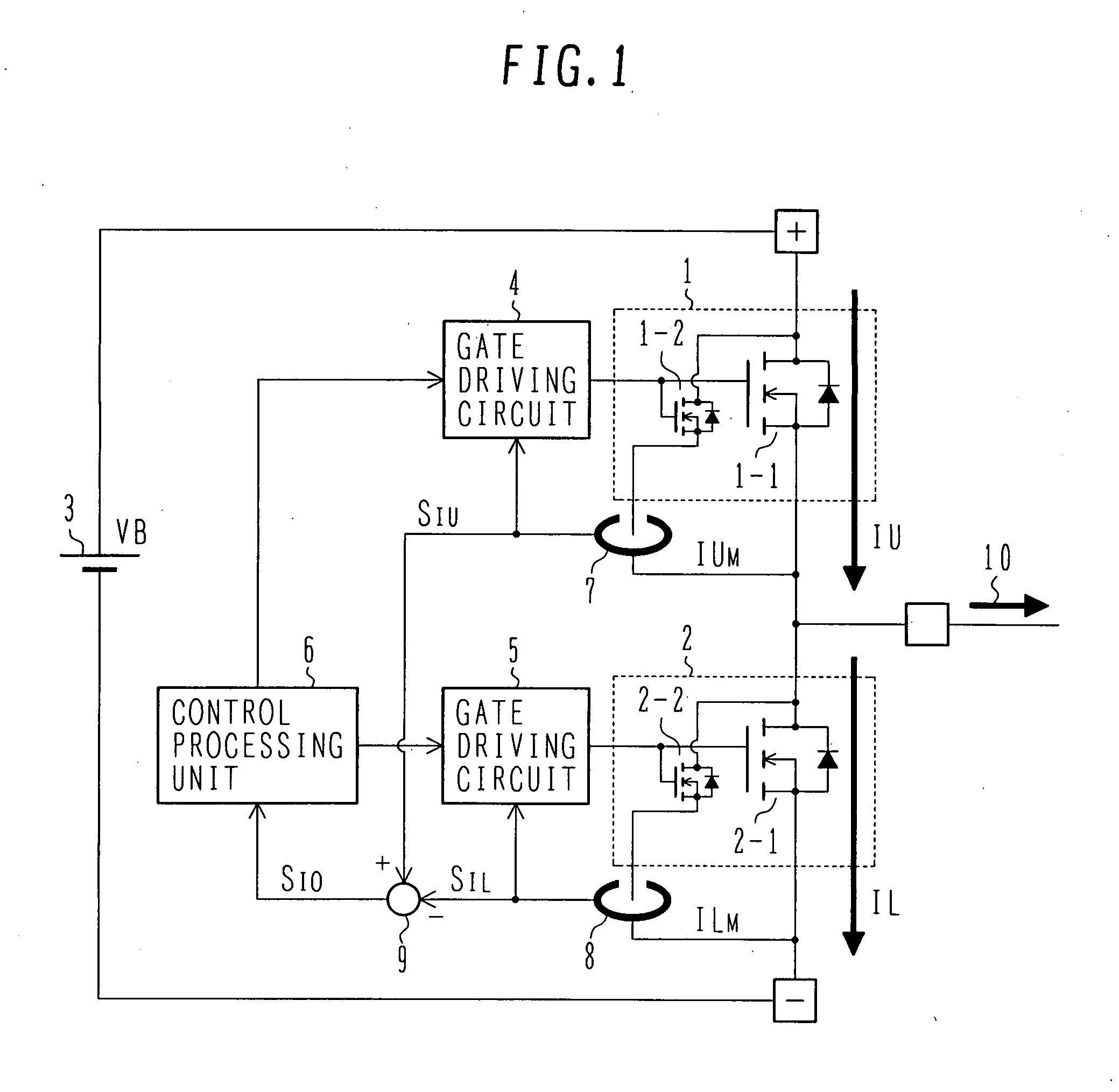
[0040]Next, a second embodiment of the present invention will be described with reference to FIG. 2.

[0041]In the second embodiment, mirror current is detected by a shunt resistor. Accordingly, as shown in FIG. 2, shunt resistors 10, 11 are inserted in the current paths of the respective mirror devices 1-2 and 2-2, and differential circuits 12 and 13 are connected to the shunt resistors 10, 11 in parallel. The other constituent elements are the same as the first embodiment shown in FIG. 1.

[0042]First, the shunt resistor 10 causes a voltage drop based on the mirror current IUM of the mirror device 1-2, and the differential circuit 12 acts to detect the voltage drop and achieve a detection signal SIU representing the current IU flowing through the switching device 1 of the upper arm. The shunt resistor 11 causes a voltage drop based on the mirror current ILM of the mirror device 2-2, and the differential circuit 13 acts to detect this voltage drop and achieve a detection signal SIL rep...

third embodiment

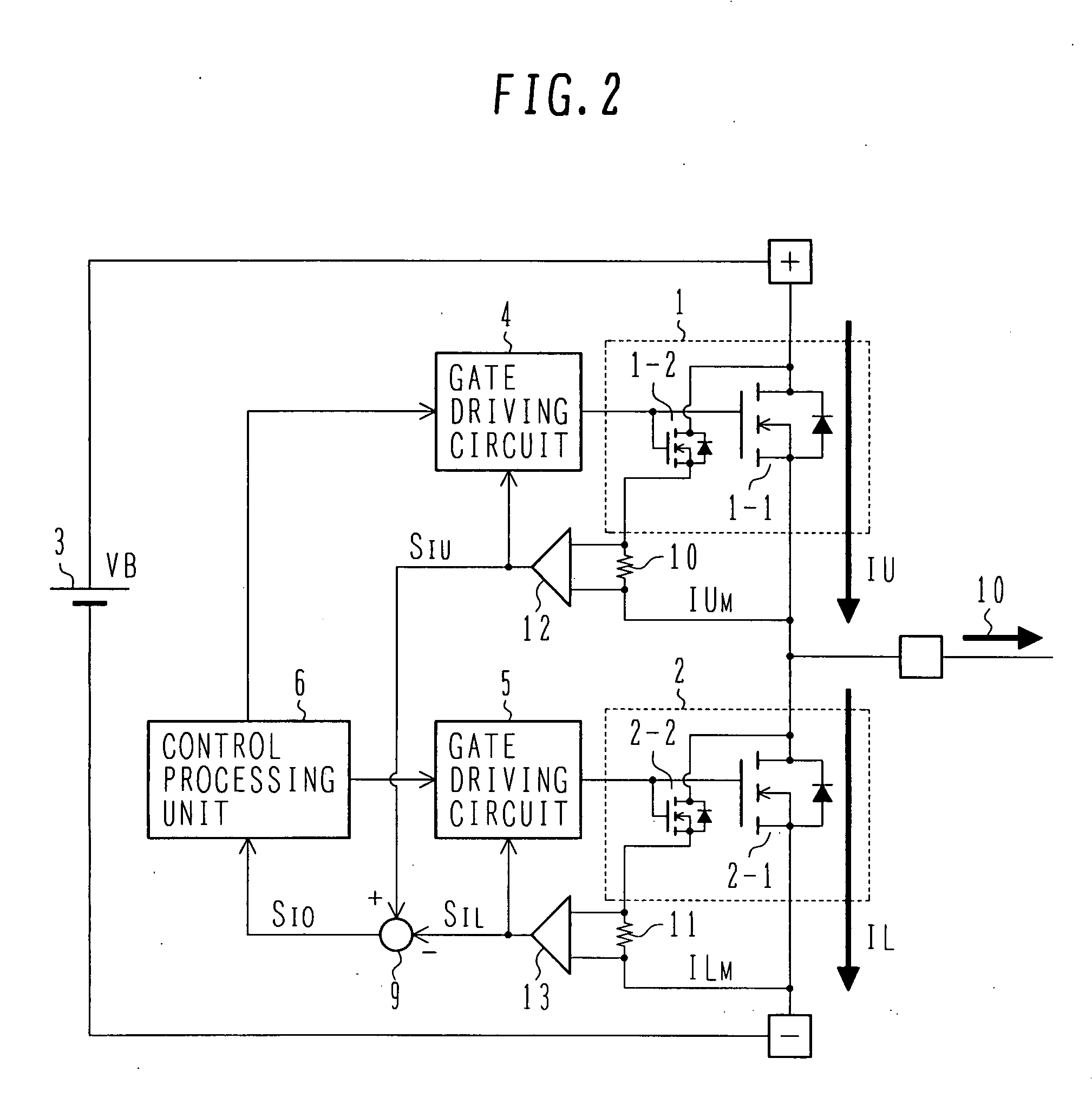
[0049]Next, a vehicle in which the power converter of the present invention is mounted will be described as a third embodiment with reference to FIG. 3. In this case, the vehicle according to the third embodiment is illustrated as a car 100, and it uses an engine 110 such as a gasoline engine or the like as a power source, for example.

[0050]When the car 100 travels, the torque of the engine 110 is transmitted to wheels WH1, WH2 through a transmission device T / M and a differential gear mechanism DEF. At this time, an M / G (dynamotor) 111 is connected to the engine 110, and M / G 111 is operated as a normal alternator, and also operated as a starter for the engine 110.

[0051]Accordingly, M / G 111 operates as the alternator (AC generator) when the engine 110 is rotating, and two secondary batteries of a main battery 120 having a terminal voltage of 36V and an auxiliary battery 121 having a terminal voltage of 12V are charged. At the start time of the engine 110, AC power is supplied from th...


PUM


Abstract

A power converter having a high side switching device and a low side switching device that are connected in series between a positive power supply terminal and a negative side power supply terminal for direct current, the connection point between the high side switching device and the low side switching device being set as an output terminal, and each of the high side switching device and the low side switching device being constructed by a switching device to which a current mirror device is appended, further including a high side current detecting unit for detecting current flowing in the current mirror device of the high side switching device, and a low side current detecting unit for detecting current flowing in the current mirror device of the low side switching device. A signal detected by the high side current detecting unit and a signal detected by the low side current detecting unit are differentiated from each other and set as a current value of the output terminal.

Description

BACKGROUND OF THE INVENTION[0001]1. Field of the Invention[0002]The present invention relates to a power converter having an output current detecting function, and particularly a power converter suitable for a servo system, a DC / DC converter, a three-phase AC inverter, etc.[0003]2. Description of the Related Art[0004]It is usually the case that in order to control a power converter for a servo system, a DC / DC converter, a three-phase AC converter or the like, it is required to detect the output current thereof, and thus various kinds of current sensors have been proposed. In this case, an insulating type current sensor having a core, so-called a hall sensor is known. Here, in the hall sensor, a conductor through which current to be measured flows is made to penetrate through a ring-shaped core, and magnetic field occurring by the current is read out by a hall sensor disposed in the magnetic path of the core, thereby detecting the current.[0005]In addition to the hall sensor describe...

Claims


Application Information

Patent Timeline
IPC IPC(8): G05F1/00
CPCH02M2001/0009H03K17/6871H03K17/0822H02M1/0009
Inventor SHIGETA, SATORUFUJINO, SHINICHIHASHIMOTO, KEITASETO, SADASHI
Owner HITACHI LTD
Why Eureka
Try Eureka