
Adaptive signal equalizer with adaptive error timing and precursor/postcursor configuration control

a signal equalizer and error timing technology, applied in the field of signal transmission and detection, can solve the problems of data symbol rates in excess of 1 gb/s becoming more susceptible to processing, and achieve the effect of minimizing timing mismatches, improving signal equalization, and substantial avoiding “drifting

Inactive Publication Date: 2007-10-04
MARVELL ASIA PTE LTD
View PDF9 Cites 26 Cited by
  • Summary
  • Abstract
  • Description
  • Claims
  • Application Information

AI Technical Summary

Benefits of technology

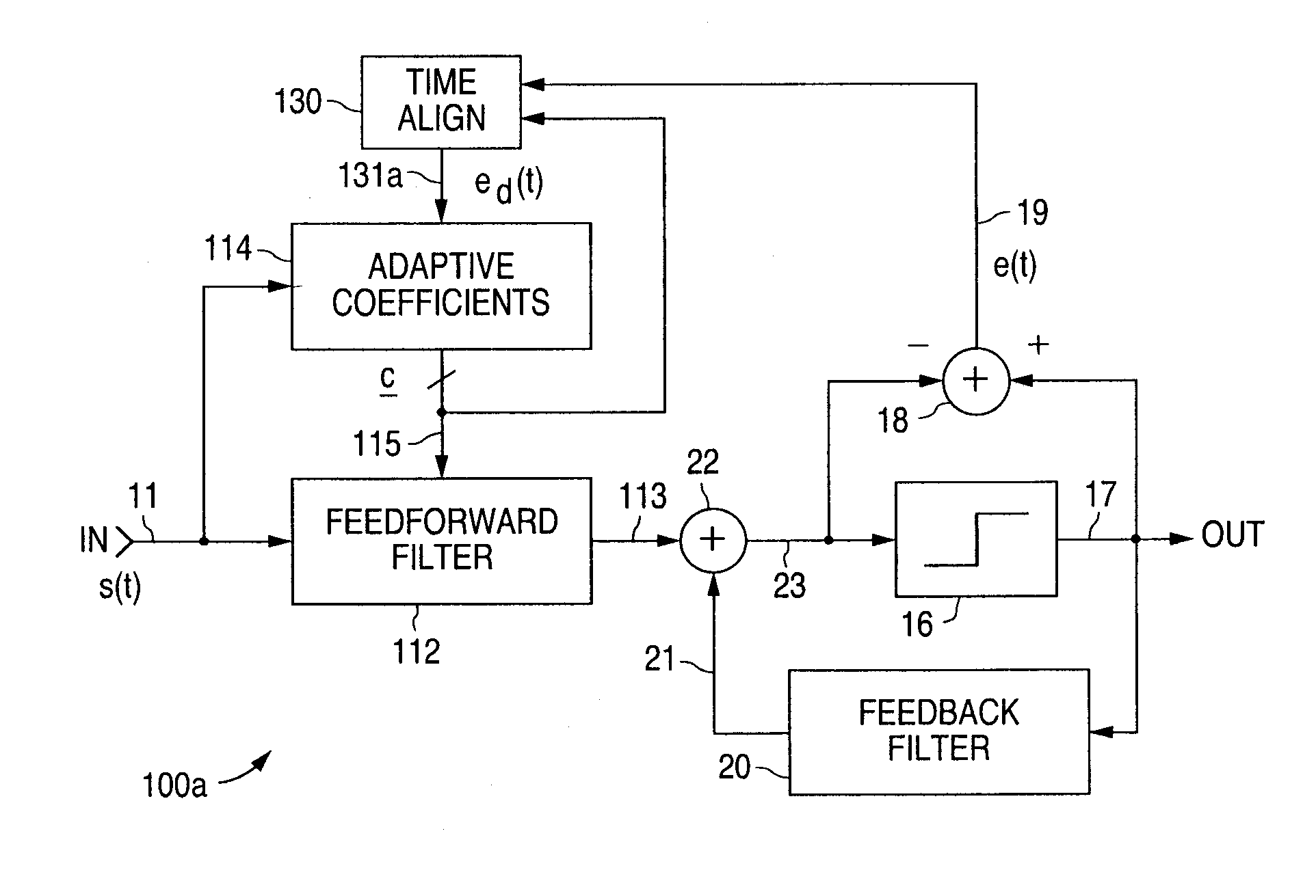
[0015] In accordance with the presently claimed invention, an adaptive signal equalizer includes a feedforward equalizer in which the feedback error signal and corresponding incoming data signal are dynamically aligned in time using signal interpolation, thereby producing more adaptive filter tap coefficient signals for significantly improved signal equalization. By dynamically minimizing timing mismatches between the feedback error signal and corresponding incoming data signal, advantages realized with the presently claimed invention include substantial avoidance of “drifting” of the adaptive filter tap coefficient signals as well as changes in the precursor / postcursor split in the feedforward equalizer, even with unknown or varying signal delays within the various signal path elements.
[0016] As will become evident from the following discussion, the presently claimed invention can be implemented and practiced in either the continuous time (e.g., analog) or discrete time (e.g., digital) domain. At the present point in time, data symbol rates less than one gigabit per second (1 Gb / s) can often be processed in either the continuous or discrete time domain, while data symbol rates greater than 1 Gb / s must generally be processed in the continuous time domain. However, as the applicable technology advances, it is expected that data symbol rates in excess of 1 Gb / s will also become more susceptible to processing in the discrete time domain as well. As will become further evident, the presently claimed invention benefits the host system or network by effectively increasing the signal-to-noise ratio (SNR), thereby reducing the bit error rate (BER) and, in turn, adding robustness (e.g., with respect to phase offsets or jitter among the data symbols). For example, in the case of a fiber optic network, such added performance and robustness will allow a longer network to be realized without a concomitant increase in network infrastructure.

Problems solved by technology

However, as the applicable technology advances, it is expected that data symbol rates in excess of 1 Gb / s will also become more susceptible to processing in the discrete time domain as well.

Method used


Image

  • Adaptive signal equalizer with adaptive error timing and precursor/postcursor configuration control
  • Adaptive signal equalizer with adaptive error timing and precursor/postcursor configuration control
  • Adaptive signal equalizer with adaptive error timing and precursor/postcursor configuration control

Examples


Embodiment Construction

[0031] The following detailed description is of example embodiments of the presently claimed invention with references to the accompanying drawings. Such description is intended to be illustrative and not limiting with respect to the scope of the present invention. Such embodiments are described in sufficient detail to enable one of ordinary skill in the art to practice the subject invention, and it will be understood that other embodiments may be practiced with some variations without departing from the spirit or scope of the subject invention.

[0032] Throughout the present disclosure, absent a clear indication to the contrary from the context, it will be understood that individual circuit elements as described may be singular or plural in number. For example, the terms “circuit” and “circuitry” may include either a single component or a plurality of components, which are either active and / or passive and are connected or otherwise coupled together to provide the described function....


PUM


Abstract

An adaptive signal equalizer with a feedforward filter in which the feedback error signal and corresponding incoming data signal are dynamically aligned in time using signal interpolation, and further, to control the precursor / postcursor filter taps configuration, thereby producing more adaptive filter tap coefficient signals for significantly improved and robust signal equalization.

Description

RELATED APPLICATIONS [0001] This is a continuation-in-part of U.S. patent application Ser. No. 10 / 290,993, filed Nov. 8, 2002.BACKGROUND OF THE INVENTION [0002] 1. Field of the Invention [0003] The present invention relates to signal transmission and detection, and in particular to adaptive signal equalization for compensation of signal distortions caused by signal dispersion and nonlinearities within signal transmission media. [0004] 2. Description of the Related Art [0005] Signal processing architectures for mitigation of different kinds of channel impairments and / or timing recovery and synchronization functions as used for communications transmission and / or storage systems can be divided into two categories: (1) discrete-time architecture (this architecture uses a sampled approach to convert the input continuous-time, analog waveform into a discrete signal and is commonly used in current systems; typically, a high resolution analog-to-digital converter, which follows the analog a...

Claims


Application Information

Patent Timeline
Patent Type & Authority Applications(United States)
IPC IPC(8): H03H7/40H03H21/00
CPCH03H21/0012H03H2021/0096H04L7/0029H04L2025/03611H04L7/0079H04L25/03057H04L2025/0349H04L7/0062
Inventor BALASUBRAMONIAN, VENUGOPALBHATTACHARJEE, JISHNUIBRAGIMOV, EDEMMUKHERJEE, DEBANJANPHANSE, ABHIJITSHANBHAG, ABHIJIT G.YU, QIAN
Owner MARVELL ASIA PTE LTD
Learn More