Fan frame structure

a technology of fan frame and fan body, which is applied in the direction of liquid fuel engines, vessel construction, marine propulsion, etc., can solve the problems of weak strength of the fan body, not all the cooling systems are able to use the big-size fans, and the noise of the radiator device, so as to promote the heat dissipation effect, reduce noise and vibration, and strengthen the frame

Inactive Publication Date: 2007-10-04
LIU WEN HAO +2
View PDF11 Cites 11 Cited by
  • Summary
  • Abstract
  • Description
  • Claims
  • Application Information

AI Technical Summary

Benefits of technology

[0010] In order to solve the preceding problems, an object of the present invention is to provide a fan frame structure with which the inner side of the fan frame expands toward the outer side thereof to the most for the flow passage thereof being able to receive a fan wheel with a bigger diameter and promoting heat dissipation effect.
[0011] Another object of the present invention is to provide a fan frame structure in which the fan frame is composed of a plastic frame part and a metal reinforcing member for strengthening the fan frame and lessening noise and vibration.
[0012] Accordingly, the fan frame structure according to the present invention includes a plastic frame member and a metal reinforcing member. The frame member has an outer side and an inner side. The inner side of the frame member defines a flow passage for receiving a fan wheel. The metal reinforcing member is joined to the frame intimately. The inner side of the frame is arranged to have a largest diameter so that the flow passage provides more space for accommodating a larger sized fan wheel. Hence, strength of the frame is reinforced, vibration and noise are reduced during a fan wheel running and integral effect of heat dissipation is enhanced largely.

Problems solved by technology

Meanwhile, noise of the radiator device is influenced directly by the running fan.
However, due to space limitation, not all the cooling systems are able to use the big sizes fan even if the smaller sized fan is unable to reach the expect effect of heat dissipation.
The fan frame with plastic material is light but the strength thereof becomes weak in case of the fan frame being changed to be thinner.
Under these circumstances, normal operation of the fan is affected significantly.
The metal fan frame provides enough strength but it is heavy and easy to produce louder noise while the air passing the fan frame to hit the inner wall of the fan frame.
In addition, the metal fan frame is more costly than the plastic fan frame and manufacturing process of the metal fan frame is more complicated than the plastic fan frame.

Method used


Image

  • Fan frame structure
  • Fan frame structure
  • Fan frame structure

Examples


Embodiment Construction

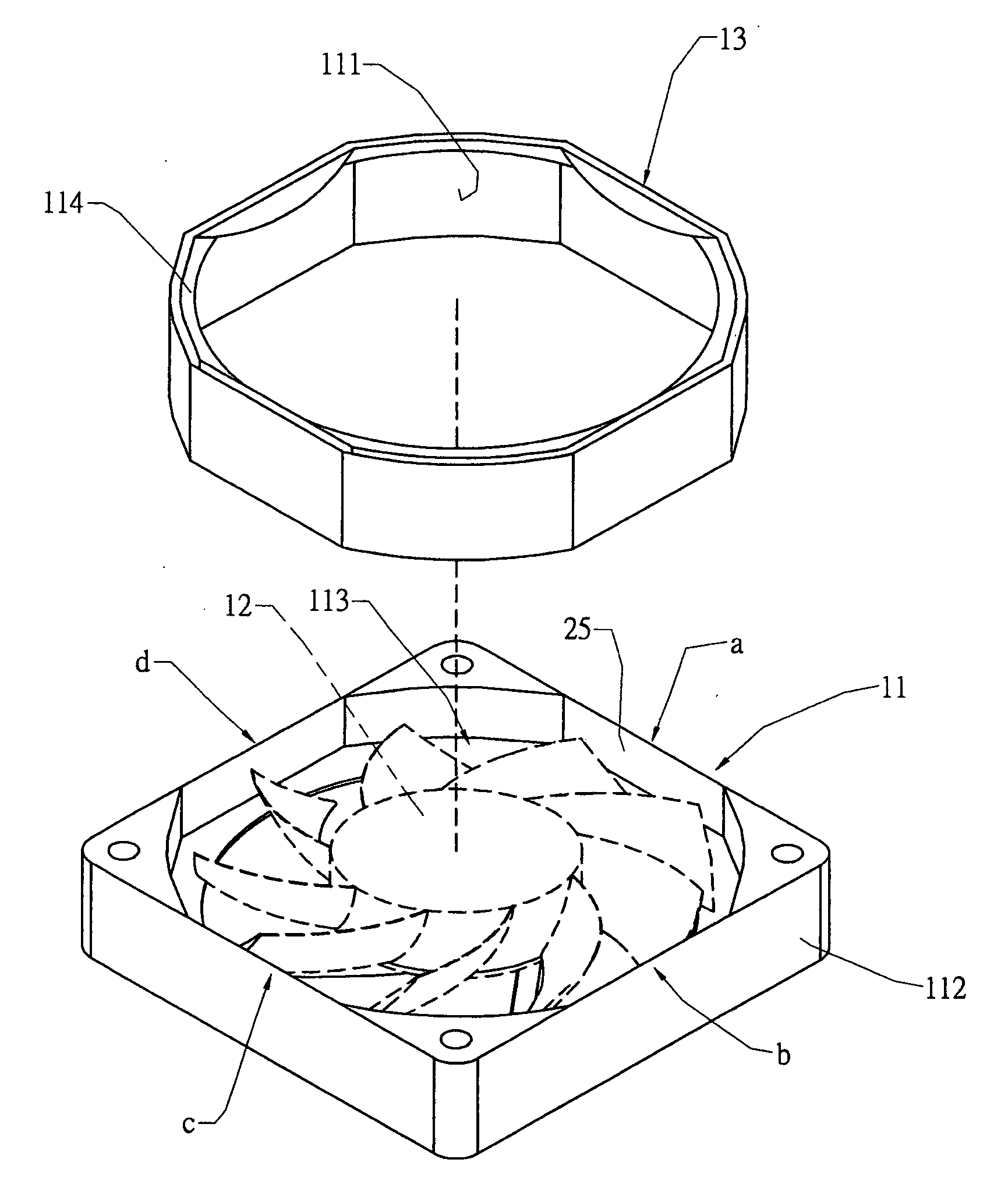
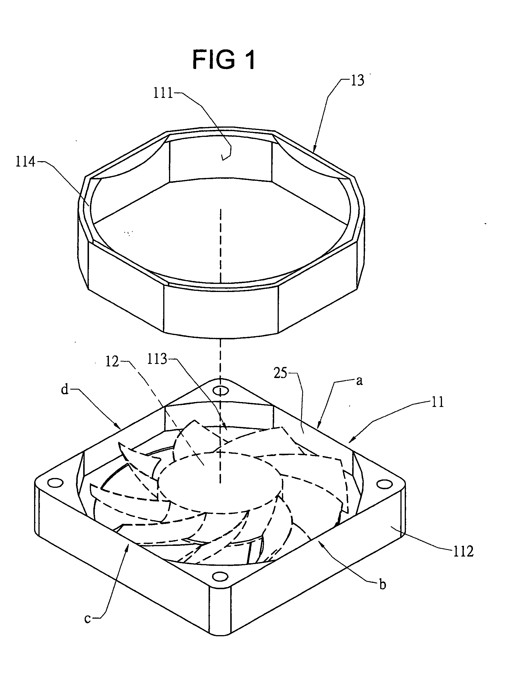
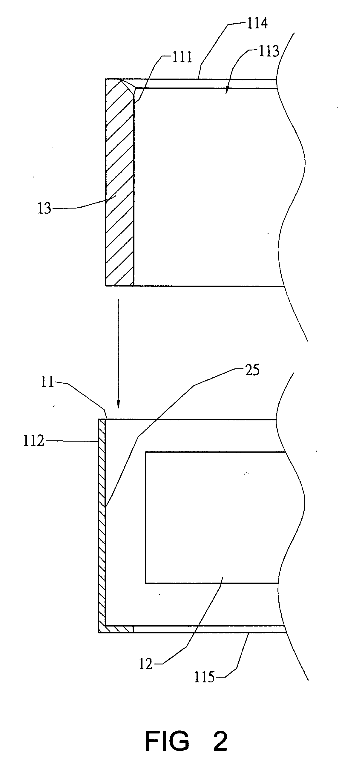
[0030] Referring to FIGS. 1 to 3, the first embodiment of a fan frame according to the present invention provides a frame member 11, which is made of plastics and has an inner frame side 111 and an outer frame side 112. The inner frame side 111 defines a space 113 for receiving a fan wheel 12. An inlet 114 and an outlet 115 are formed at two lateral sides of the space 113 respectively. The outer frame side 112 defines the size of the frame member 11. The frame member 11 has a receiving part 25 for accommodating a metal reinforcing member 13, which is shaped as strip ring, such that once the metal reinforcing member 13 is joined to the frame member 11 tightly, the metal reinforcing member 13 constitutes the inner frame side 111 to face the fan wheel 12 for strengthening the frame member 11.

[0031] The plastic frame member 11 provides a gross volume greater than the metal reinforcing member 13. Each of the four sides of the frame member 11 provides the shortest distance between the fr...


PUM


Abstract

A fan frame structure includes a plastic frame and a metal reinforcing member. The inner side of the frame defines a flow passage for receiving a fan wheel. The metal reinforcing member is joined to the frame intimately. The inner side of the frame is arranged to have a largest diameter so that the flow passage provides more space for accommodating a larger sized fan wheel. Hence, strength of the frame is reinforced, vibration and noise are reduced during a fan wheel running and integral effect of heat dissipation is enhanced largely.

Description

BACKGROUND OF THE INVENTION [0001] 1. Field of the Invention [0002] The present invention is related to a fan frame structure and particularly to a fan frame, which provides a plastic frame part and a metal reinforcing member. [0003] 2. Brief Description of the Related Art [0004] The fan is an essential part of air cooling radiator device and plays an important role for heat dissipation effect. The fan is the only movable part in the radiator device. Meanwhile, noise of the radiator device is influenced directly by the running fan. The fan induces air to move through the cooling fins with a specific speed and a specific way for heat exchange being performed between the air and the cooling fins such that accumulated heat at the cooling fins can be carried away to achieve heat removal with forced convection. [0005] Air flow and air pressure decide a fan being strong or weak. The air flow refers a product of an area of the air passing through and a velocity of the air passing through t...

Claims


Application Information

Patent Timeline
Patent Type & Authority Applications(United States)
IPC IPC(8): B63H1/16
CPCF04D29/023H05K7/20172F04D29/526F05D2300/43F05D2300/603F05D2300/702
Inventor LIU, WEN-HAOYU, SHOU-TECHANG, BOR-HAW
Owner LIU WEN HAO
Why Eureka
Try Eureka