Fan cover structure

a technology of fan cover and cover plate, which is applied in the direction of marine propulsion, liquid fuel engine, vessel construction, etc., can solve the problems of reducing the life span of electronic products, affecting the service life of electronic products, and the heat generated by running electronic components, etc., and achieves the effect of simple structure, easy assembly and convenient fixing on the casing

Inactive Publication Date: 2007-10-04
INVENTEC CORP
View PDF6 Cites 8 Cited by
  • Summary
  • Abstract
  • Description
  • Claims
  • Application Information

AI Technical Summary

Benefits of technology

[0009] In light of the shortcomings of the prior arts, the main objective of the present invention is to provide a fan cover structure that has simple structure, can be assembled easily, and installed without assistance tools.
[0010] Another objective of the present invention is to provide a fan cover structure that can be fixed on the casing easily, and can reduce the noises resulted from the vibration of fan.
[0011] A further objective of the present invention is to provide a fan cover structure that can utilize the space for installation efficiently and can be cost-effective as well.
[0012] To achieve the above objectives, the present invention provides a fan cover structure that can be installed at the draft direction of a fan, and allows the fan to be fixed on the casing; it comprises: a mesh frame; a latching component that protrudes vertically from the edge of the mesh frame; the fixing opening that is used to fix the mesh frame onto the preset frame of the fan; an extension part that protrudes from the bottom of the mesh frame, a tooling hole is also formed at the center of the extension part, so that the fan can be connected to the preset tooling pin on the casing by the tooling hole; as well as a flexible component that protrudes from the top of the mesh frame, which is set against the top cover of the casing and used to reduce the vibration of the fan. Additionally, the fan cover structure further comprises a handle that is formed at the top of the mesh frame, which allows the user to remove the fan by hand. Therefore, the present invention allows the fan to be assembled, as well as installed into and removed from the casing without the assistance of tools, it does not take up additional space for installation and is cost-effective, which satisfies the demand of users.
[0013] In addition, according to the present invention, the tooling hole and the tooling pin of the fan co

Problems solved by technology

However, as the development of electronic components continues, the problem of how to deal with the heat generated from running the electronic components also needs to be considered.
If the heat is allowed to accumulate inside of an electronic product and is not dissipated to the surrounding atmosphere in time, the internal electronic components or parts may be damaged, which in turn reduces the life span of the electronic products.
But since holding frame 13 is used to support heat sink fan module 1, hence its size needs to be larger than that of heat sink fan module 1, and because holding frame 13 also needs to be fixed firmly, a latching part 141 must be formed on casing 14, which in turn takes up larger space in casing 14 and leads to problems like less useable space in casing 14 and higher production cost for casing 14.
On the other hand, heat sink fan 10, frame 11 and protective mesh of heat sink fan module 1 described above have to be assembled by using tools, which makes the assemblage of fan more inconvenient.

Method used


Image

  • Fan cover structure
  • Fan cover structure
  • Fan cover structure

Examples


Embodiment Construction

[0020] The invention has been described using exemplary preferred embodiments; anyone who is familiar with the arts can easily comprehend other advantages and effects of the present invention by reading the disclosed content in this claim. Moreover, the present invention can also be implemented or applied by using other embodiments, and anyone can modify and adjust the details in this claim on the basis of different considerations or applications, provided that he or she does not depart from the purpose and scope of the present invention. It should be noted that the figures in this claim are only simple examples and were not drawn according to actual size, which means the figures do not reflect the actual size of the relevant structures.

[0021] The following embodiments are only used to elucidate the present invention, and are not to be used to limit the scope of it.

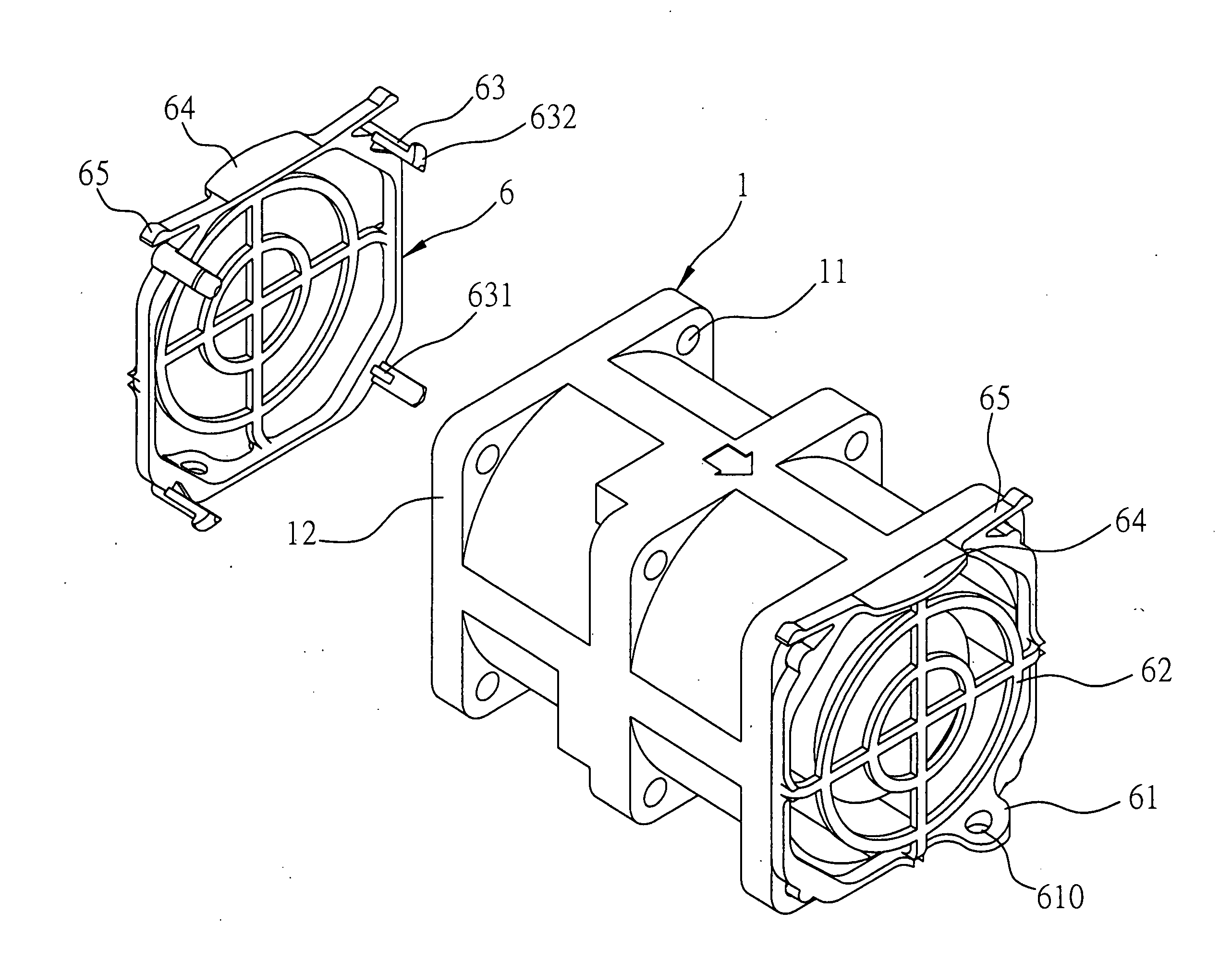
[0022] Referring to FIG. 3, which is a schematic view showing the fan cover structure of the present invention to be ...


PUM


Abstract

A fan cover structure installed in a draft direction of a fan and for fixing the fan to a casing, includes: a mesh frame; a plurality of latching components that protrude outwards and are perpendicular to the edge of the mesh frame, so as to fix the mesh frame to preset fixing openings of the fan; an extension part that protrudes from the bottom of the mesh frame, and formed with a tooling hole, so that the fan can be connected to a preset tooling pin on the casing by the tooling hole; and a flexible component that protrudes from the top of the mesh frame and abuts against a top cover of the casing so as to reduce vibration from the fan. The fan cover structure facilitates the installation and removal of the fan.

Description

FIELD OF THE INVENTION [0001] The present invention is related to fan cover structures, and more particularly, to a fan cover structure that can be installed at the draft direction of a fan, and can allow a fan to be fixed on the casing. BACKGROUND OF THE INVENTION [0002] In a technologically advanced society where information flows freely, the computer is gradually becoming an indispensable electronic product for the common people, and the server has become the integral part to the provision of various services. But as the computer industry becomes ever more advanced, the development of electronic components also proceed toward the direction of higher level and higher integration, so that the demand of consumers can be satisfied and high computing speed can be attained. [0003] However, as the development of electronic components continues, the problem of how to deal with the heat generated from running the electronic components also needs to be considered. For example, the computin...

Claims


Application Information

Patent Timeline
IPC IPC(8): F04D29/70
CPCF04D19/007F04D29/703F04D29/646
Inventor CHUANG, CHIH-PENG
Owner INVENTEC CORP
Why Eureka
Try Eureka