Polishing method and polishing apparatus

a polishing apparatus and polishing method technology, applied in the direction of manufacturing tools, cleaning using liquids, abrasive surface conditioning devices, etc., can solve the problems of difficult to completely remove foreign matter adhering to the polishing member, uneven rubbing of the polishing member with a brush, and difficult to remove foreign matter from the polishing member, etc., to achieve the effect of preventing foreign matter adhesion

Inactive Publication Date: 2007-10-04
EBARA CORP
View PDF15 Cites 32 Cited by
  • Summary
  • Abstract
  • Description
  • Claims
  • Application Information

AI Technical Summary

Benefits of technology

[0012]The present invention has been made in view of the above situation in the related art. It is therefore an object of the present invention to provide a polishing method and a polishing apparatus which can prevent scratches in a polished surface of a polishing object, caused by foreign matter adhering to a surface of a polishing member, thus preventing the attendant lowering of the yield even when the polishing object is large-sized, an adhesion region specifying method and an adhesion region specifying apparatus for specifying a foreign matter adhesion region, a program for carrying out the polishing method and a program for carrying out the adhesion region specifying method, and storage media storing the programs.
[0086]By thus storing the program in a computer readable storage medium and reading the program from the storage medium for causing a computer to control an apparatus, a polishing apparatus, which can prevent the lowering of the yield due to scratches, can be provided.

Problems solved by technology

It is, however, difficult to completely remove foreign matter adhering to a polishing member so as to fully prevent scratches producing in a surface (polished surface) of a polishing object after polishing.
This is partly because, with the trend toward larger-sized polishing objects, an area of a polishing member for contact with a surface (to be polished) of a polishing object becomes larger, whereby blowing of a cleaning liquid onto the polishing member, rubbing of the polishing member with a brush, etc. are likely to be uneven, making effective removal of foreign matter from the polishing member difficult.
On the other hand, uniform cleaning of a surface of a polishing member, if possible, may result in a failure in intensively cleaning a foreign matter adhesion portion of the polishing member, leading to insufficient removal of foreign matter from the polishing member.
The analysis method and apparatus are therefore considered not to be capable of promptly dealing with the occurrence of scratches in a surface of a polishing object in a polishing apparatus operating in a mass production line.
Prevention of the lowering of the yield will thus not be possible.

Method used


Image

  • Polishing method and polishing apparatus
  • Polishing method and polishing apparatus
  • Polishing method and polishing apparatus

Examples


Embodiment Construction

[0107]Preferred embodiments of the present invention will now be described with reference to the drawings.

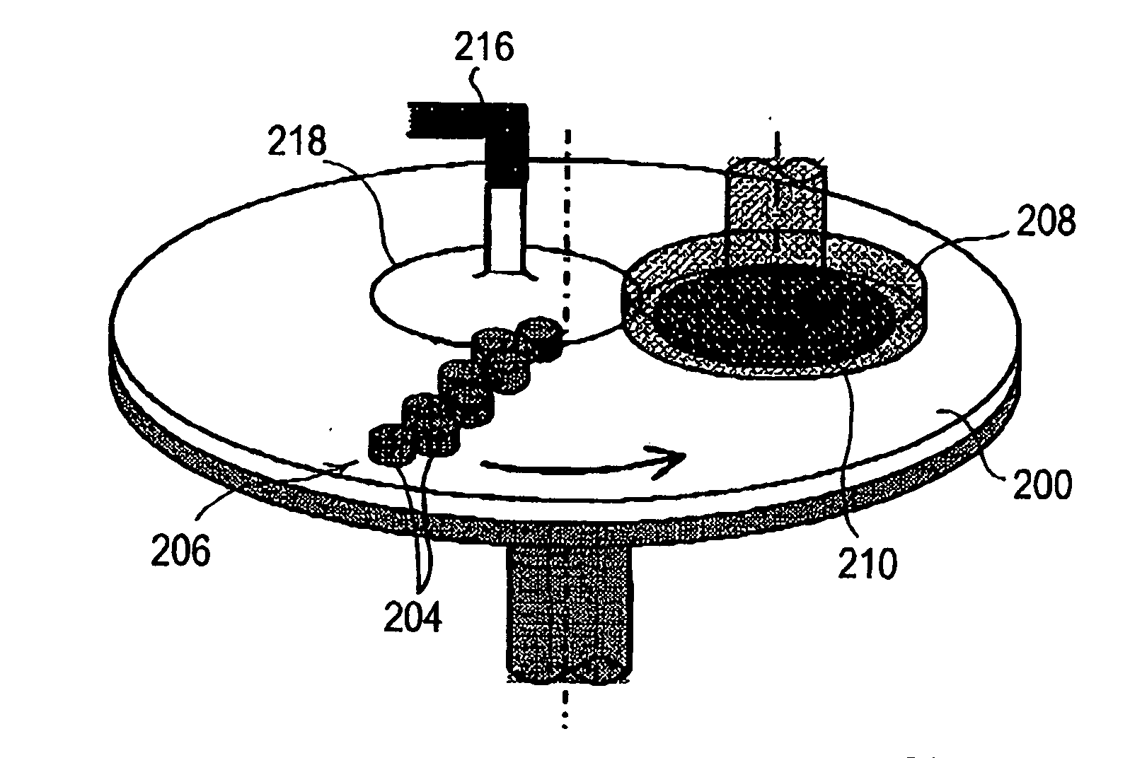
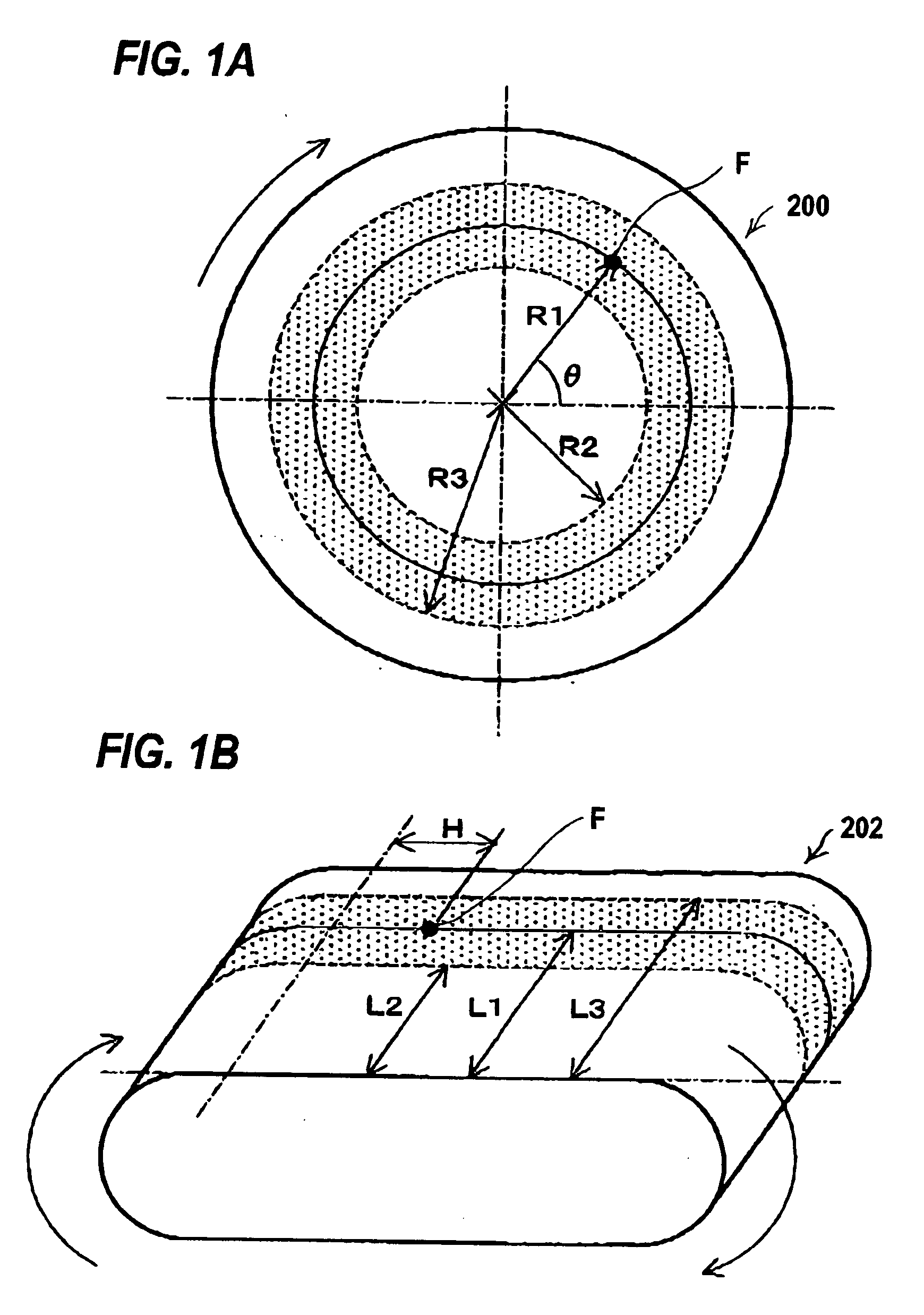
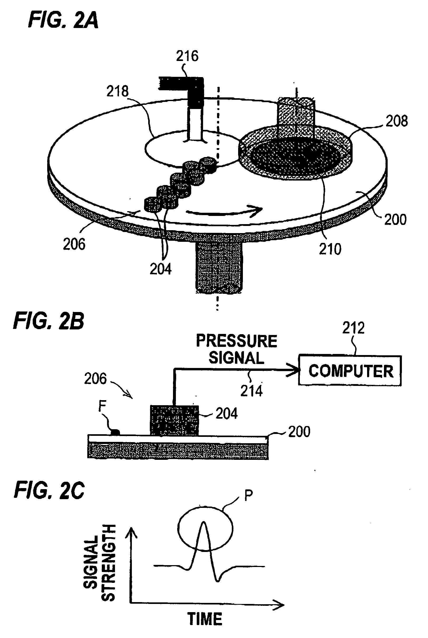
[0108]At the outset, the terms “foreign matter adhesion position” and “foreign matter adhesion area”, in a surface of a polishing member, such as a polishing pad, to which foreign matter is adhering, will be described with reference to FIGS. 1A and 1B. In general, a polishing member, such as a polishing pad, is not in a fixed or stationary state during polishing, but is making a rotational movement in the case of a rotary polishing member 200, as shown in FIG. 1A, or a linear movement in the case of an endless belt-type polishing member 202, as shown in FIG. 1B.

[0109]The term “foreign matter adhesion position” refers to the exact position of adherent foreign matter in a surface of a polishing member. Thus, as shown in FIG. 1A, when a fixed reference coordinate system (polar coordinate system is illustrated in the Figure) is taken on the surface of the rotary polishing member 200...


PUM

PropertyMeasurementUnit
angleaaaaaaaaaa
angleaaaaaaaaaa
radius R1aaaaaaaaaa

Abstract

A polishing method can prevent scratches in a polished surface of a polishing object, caused by foreign matter adhering to a surface of a polishing member, thus preventing the attendant lowering of the yield even when the polishing object is large-sized. The polishing method includes: specifying a foreign matter adhesion position or a foreign matter adhesion area in a surface of the polishing member; and intensively cleaning the foreign matter adhesion position or the foreign matter adhesion area in the surface of the polishing member.

Description

BACKGROUND OF THE INVENTION[0001]1. Field of the Invention[0002]The present invention relates to a polishing method and a polishing apparatus for polishing optical components, machine components, ceramics, metals, etc., a program for carrying out the polishing method, and a storage medium storing the program, and more particularly to a polishing method and a polishing apparatus which are suitable for polishing a polishing object, such as a semiconductor wafer, into a flat mirror-like surface, a program for carrying out the polishing method, and a storage medium storing the program.[0003]2. Description of the Related Art[0004]With the recent progress toward higher integration of semiconductor devices, circuit interconnects are becoming finer and the sizes of devices integrated are becoming smaller. The manufacturing of such semiconductor devices necessitate a process of removing by polishing a film formed in a surface of a semiconductor wafer, thereby flattening the surface. There ar...

Claims


Application Information

Patent Timeline
Patent Type & Authority Applications(United States)
IPC IPC(8): B24B1/00
CPCB08B1/04H01L21/67219B24B53/017B08B3/02
Inventor FUKUDA, AKIRAHIYAMA, HIROKUNITSUJIMURA, MANABU
Owner EBARA CORP
Why Eureka
Try Eureka