System and method of recording and displaying in context of an image a location of at least one point-of-interest in a body during an intra-body medical procedure

a technology a context, which is applied in the field of system and method of recording and displaying in context of an image a location of at least one point of interest in a body during an intra-body medical procedure, can solve the problems of high subjective visual memorization, inability to teach the co-establishment of the location of the imaging apparatus or the image, and inability to image hardly or not at all

Inactive Publication Date: 2007-10-04
SUPERDIMENSION LTD
View PDF41 Cites 169 Cited by
  • Summary
  • Abstract
  • Description
  • Claims
  • Application Information

AI Technical Summary

Benefits of technology

[0083] According to yet a further aspect of the present invention there is provided a method of determining an angle between a surface of a body cavity and a catheter, the method comprising the steps of (a) establishing a location of the body; (b) defining a plurality of projection planes of the body; (c) inserting the catheter into the body cavity and establishing a location of the catheter; (d) projecting at least a portion of the catheter on each of the plurality of projection planes; and (e) projecting at least one line along the surface on the plurality of projection planes; such that, in course of guiding the catheter, the location of the body, the catheter and the line are known, thereby an angle between the catheter and the line is definable.
[0084] According to still a further aspect of the present invention there is provided a system for determining an angle between a surface of a body cavity and a catheter, the system comprising (a) a mechanism for establishing a location of the body; (b) a mechanism for defining a plurality of projection planes of the body; (c) a mechanism for establishing a location of a catheter insertable into the body cavity; (d) a mechanism for projecting at least a portion of the catheter on each of the plurality of projection planes; and (e) a mechanism for projecting at least one line along the surface on the plurality of projection planes; such that, in course of guiding the catheter, the location of the body, the catheter and the line are known, thereby an angle between the catheter and the line is definable.

Problems solved by technology

However, the prior art fails to teach the co-establishment of the location of the imaging apparatus or the image coordinates, such that points-of-interest in the body are recordable, displayable and most importantly projectable onto an image of the body of the patient taken from another angle during the same procedure or during another, later procedure.
Cardiac arrhythmia is the result of improper progression of electrical signals for contraction along the heart tissue.
According to the present methodology, knowing the three dimensional location of the steerable catheter tip within the heart cavity depends on a large number of data parameters and visual memorization and is therefore highly subjective.
In addition, the heart tissue itself is transparent to X-rays and it is therefore hardly or not at all imageable.
These difficulties are more critical when it is required to return accurately to a location already mapped for further treatment.
This, in turn, is associated with a major limitation because it is in many cases advantageous to image the patient from different angles, so as to obtain images of different planes thereof.
Yet, any catheter location data (point-of-interest) recorded in context of an image obtained from a certain relative orientation is non-projectable onto images obtained from other orientations, because the location in space of the imaging device is not monitored or established.
The above apparatuses and methods, while teaching the recording of heart functionality for identifying active sites therein, fail to teach the recording of other points-of-interest, such as, but not limited to, points to which ablation has been applied, therefore preventing the accurate relocation of such sites for nearby ablation as required from time to time.

Method used


Image

  • System and method of recording and displaying in context of an image a location of at least one point-of-interest in a body during an intra-body medical procedure
  • System and method of recording and displaying in context of an image a location of at least one point-of-interest in a body during an intra-body medical procedure
  • System and method of recording and displaying in context of an image a location of at least one point-of-interest in a body during an intra-body medical procedure

Examples


example

[0258] Reference is now made to the following example, which together with the above descriptions, illustrate the invention in a non limiting fashion.

[0259] This example is directed at measuring parameters required for fluoroscope imaging according to the present invention.

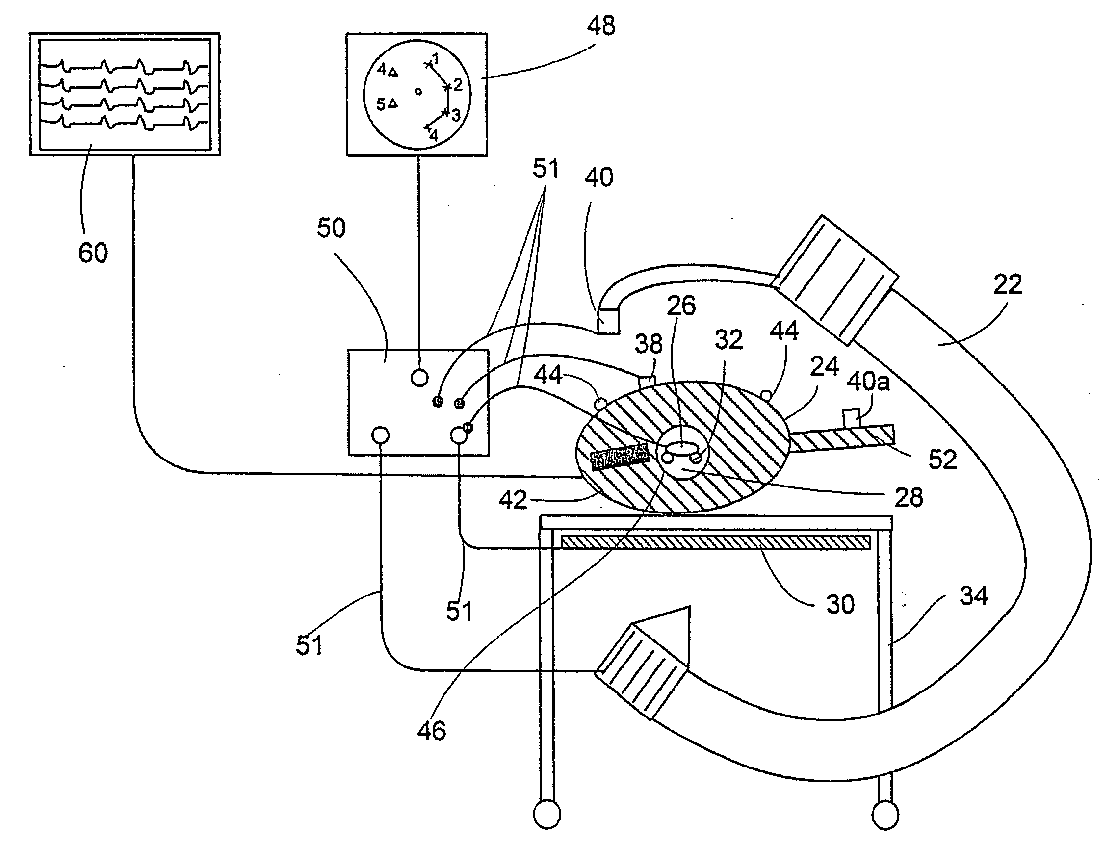
[0260] Assume a first system of coordinates {K,L,F} which defines the location of an of an imaging instrument, say a fluoroscope having a source and an imaging plane.

[0261] Assume a second system of coordinates {X,Y,Z} which defines the location of a location implement.

[0262] Define {k0,l0,f0} as the origin of the {X,Y,Z} system as reflected on the {K,L,F} system of coordinates.

[0263] The {X,Y,Z} system is rotated with respect to the {K,L,F} system. The rotation operator, T, is a matrix of 3×3 terms which satisfies the orthonormality condition.

[0264] The location implement implemented in the catheter is at {x,y,z} as measured in the {X,Y,Z} system.

[0265] The location implement is imageable and therefore wil...


PUM


Abstract

A method of displaying at least one point-of-interest of a body during an intra-body medical procedure. The method is effected by (a) establishing a location of the body; (b) establishing a location of an imaging instrument being for imaging at least a portion of the body; (c) defining at least one projection plane being in relation to a projection plane of the imaging instrument; (d) acquiring at least one point-of-interest of the body; and (e) projecting said at least one point-of-interest on said at least one projection plane; such that, in course of the procedure, the locations of the body and the imaging instrument are known, thereby the at least one point-of-interest is projectable on the at least one projection plane even in cases whereby a relative location of the body and the imaging instrument are changed.

Description

[0001] This is a Continuation of U.S. patent application Ser. No. 10 / 445,357, filed May 27, 2003, which is Continuation of U.S. patent application Ser. No. 09 / 463,176, filed Jan. 21, 2000, which is national phase of PCT / IL99 / 00512, which claims priority from: Israel patent application 126333 filed Sep. 24, 1998 (now abandoned), U.S. patent application Ser No. 09 / 179,827 filed Oct. 28, 1998 (patented) and U.S. provisional application No. 60 / 142,976 filed Jul. 1, 1999.FIELD AND BACKGROUND OF THE INVENTION [0002] The present invention relates to a system and method of recording and displaying in context of an image a location of at least one point-of-interest in a body during an intra-body medical procedure, and, more particularly, to a system and method which enable to simultaneously obtain location data of the body, of a catheter inserted into the body and of an imaging instrument used to image the catheter and the body, to thereby record and display in context of the image the locat...

Claims


Application Information

Patent Timeline
Patent Type & Authority Applications(United States)
IPC IPC(8): A61B5/05A61B5/06A61B5/296A61B6/00A61B6/12A61B19/00A61M25/00A61M25/01G06T1/00G06T7/60
CPCA61B19/52A61B5/06A61B90/36A61B5/062A61B5/064
Inventor GILBOA, PINHASTOLKOWSKY, DAVIDHOLLANDER, DAVID
Owner SUPERDIMENSION LTD
Why Eureka
Try Eureka