Ultrasound endoscope

Active Publication Date: 2007-10-04
FUJIFILM CORP
View PDF5 Cites 16 Cited by
  • Summary
  • Abstract
  • Description
  • Claims
  • Application Information

AI Technical Summary

Benefits of technology

[0017]The terminal passage of the biopsy channel is formed internally of a casing of the rigid tip end section in the form of a sloped passage turning upward or radially outward in the forward direction to guide an inserted medical instrument along the sloped passage. The longer the length of the guide passage, the higher becomes the stability of a medical instrument which is manipulated by an operator for protrusion into a body cavity. In the terminal passage leading to the instrument outlet of the biopsy channel, actually an inserted medical instrument is guided by a sloped passage portion which rises upward or radially outward in the forward direction, and not guided by other portions of the passage. Therefore, the terminal passage of the biopsy channel can be elongated by opening the instrument outlet in the flat top surface of the plateau which is disposed parallel with the longitudinal axis of the rigid tip end section, as compared with a case where the instrument outlet i

Problems solved by technology

Further, the view field of the optical observation means can be limited depending upon the position of the instrument outlet which is opened in a casing wall of the rigid tip end section.
If an inserted medical instrument gets out of the view field of the optical observation means over a certain distance after extrusion from the instrument outlet in the casing of the rigid tip end section, the unguided blind distance might give rise to not only safety problems but also problems in sta

Method used


Image

  • Ultrasound endoscope
  • Ultrasound endoscope
  • Ultrasound endoscope

Examples


first embodiment

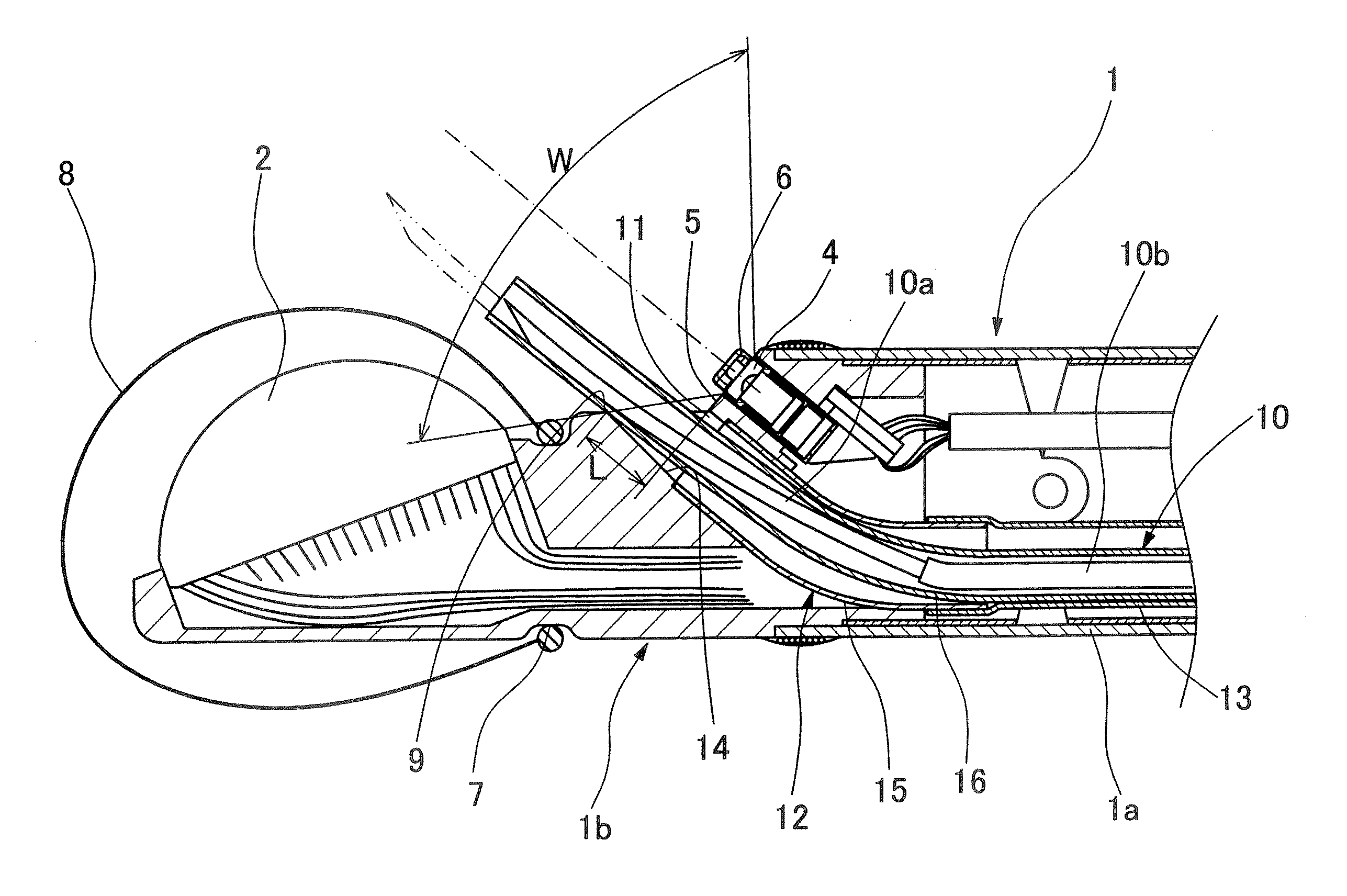
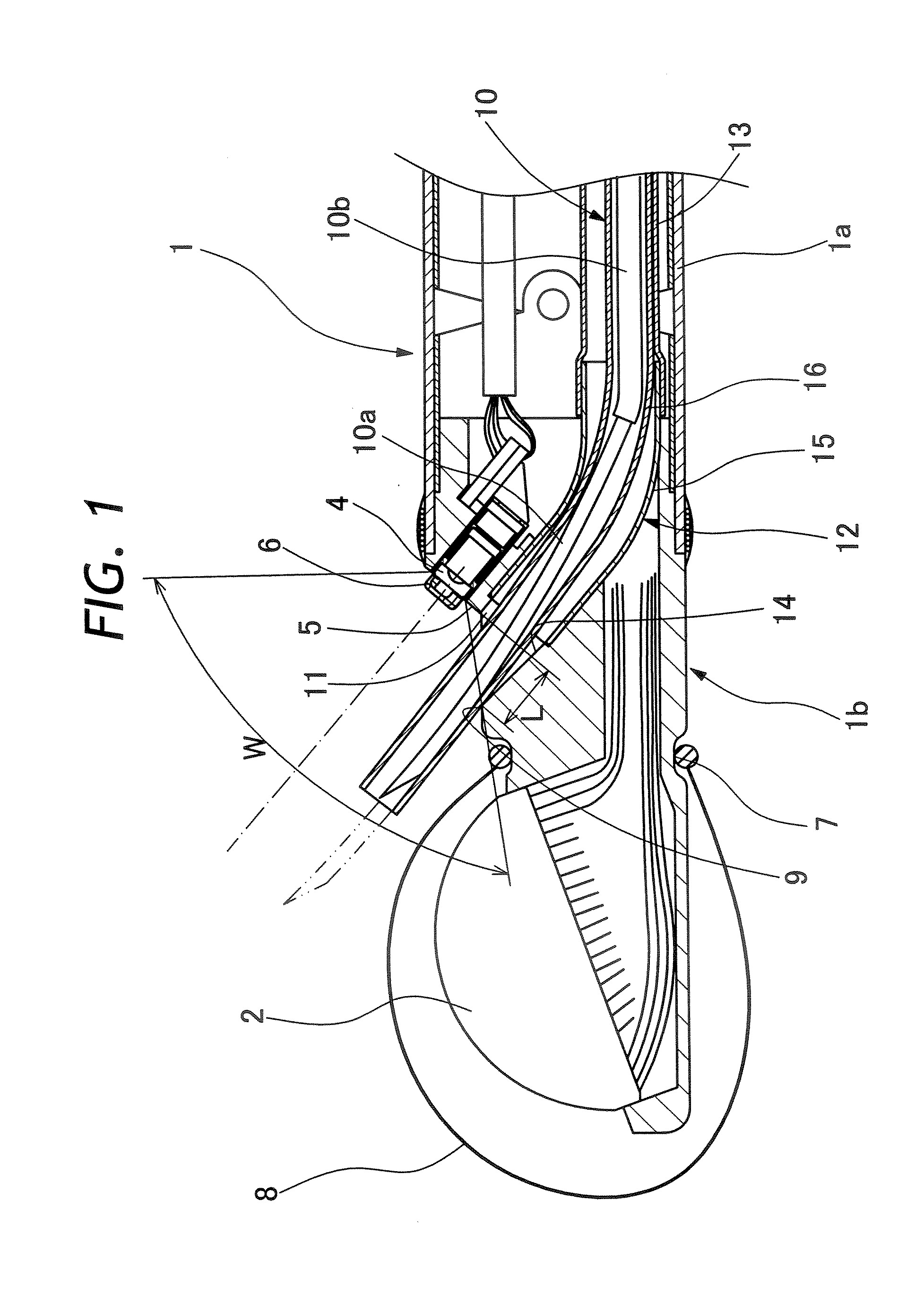
[0036]Hereafter, the present invention is described more particularly by way of its preferred embodiments with reference to the accompanying drawings. Referring first to FIGS. 1 to 3, there is shown an ultrasound endoscope according to the present invention. More specifically, shown in FIG. 1 is a longitudinal sectional view of a rigid tip end section of an endoscopic insert section, and in FIG. 2 a plan view of the same rigid tip end section.

[0037]As clear from these figures, an ultrasound examination means and an optical observation means are mounted on a rigid tip end section 1b which connected to the fore end of a bending section 1a of an insert section 1. The ultrasound examination means is constituted by an ultrasound transducer 2 with a large number of ultrasound transducer elements arrayed in the axial direction of the rigid tip end section 1b. The transducer elements of the ultrasound transducer 2 are arranged in an array which is extended axially from a position near a for...

second embodiment

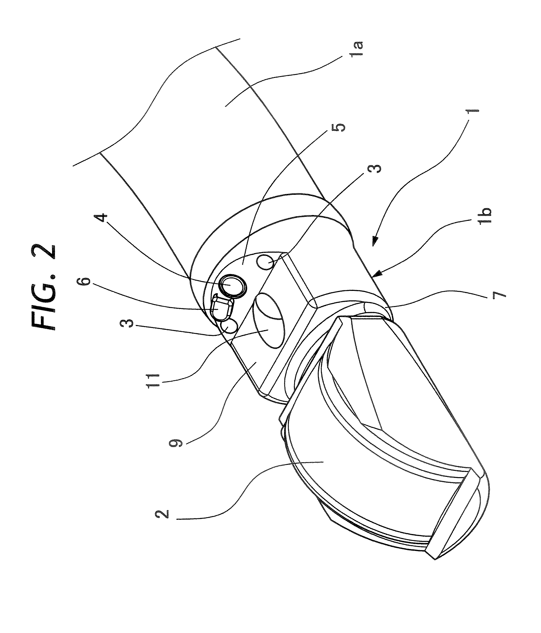
[0051]In this regard, it suffices for the plateau 9 to have a flat top surface which is wider than the diameter of the instrument outlet opening 11. In other words, the flat top surfaces of the plateau 9 on the opposite sides of the instrument outlet opening 11 are not necessarily required to be extended up to the outer periphery of the rigid tip end section 1b. In a second embodiment shown in FIGS. 7 to 9, opposite sides of a plateau 20 are cut off obliquely to present a trapezoidal shape as a whole. In this case, the flat top surface of the plateau 20 is limited to a minimum area which is necessary for containing the instrument outlet opening 11, and receded light guide walls 21 are provided on the opposite sides of the plateau 20 evade illumination light which is cast from the illumination windows 3. The receded light guide walls 21 at the opposite lateral sides of the plateau 20 are so shaped as to provide a broader unblocked space in front of the illumination windows 3.

[0052]As...


PUM


Abstract

An ultrasound endoscope having an ultrasound transducer mounted on a rigid tip end section at the distal end of an elongated endoscopic insert section, on the front side of a inclined casing wall section in which illumination windows and an optical image pickup assembly are fitted. For protrusion of a medical instrument into a body cavity, an instrument outlet of a biopsy channel is opened in a casing of the rigid tip end section in an obliquely upward direction from behind the ultrasound transducer. As far as a proximal end of the rigid tip end section, the biopsy channel is constituted by a flexible tube which is extended in the axial direction of the insert section and joined by way of a curved connecting pipe with a terminal passage which is formed internally of a casing of the rigid tip end section and inclined relative to the longitudinal axis of the latter. The instrument outlet is opened in a flat top surface of a plateau which is provided on the casing of the rigid tip end section on the rear side of the ultrasound transducer, the flat top surface of said plateau being located at a level lower than a top end the ultrasound transducer and the illumination windows fitted in the inclined casing wall section.

Description

BACKGROUND OF THE INVENTION[0001]1. Field of the Art[0002]This invention relates to an ultrasound endoscope having an electronic scan type ultrasound transducer incorporated into a rigid tip end section at the distal end of an elongated insert section along with an optical observation means.[0003]2. Prior Art[0004]Ultrasound endoscopes have both an optical observation means and an ultrasound examination means on a rigid tip end section of an elongated flexible insert section to be inserted into a body cavity. The optical observation means is composed of illumination components and an optical image pickup system for observation of intracavitary sites of interest. Normally, picture images of an intracavitary site are captured by a solid-state image sensor. On the other hand, the ultrasound examination means is constituted by an ultrasound transducer which is categorized either as a mechanical scan type or as an electronic scan type depending upon the operating mode of the ultrasound t...

Claims


Application Information

Patent Timeline
IPC IPC(8): A61B8/14
CPCA61B1/018A61B8/12A61B8/4488A61B8/445A61B1/00144A61B1/00177A61B1/0008
Inventor KOHNO, SHINICHI
Owner FUJIFILM CORP
Why Eureka
Try Eureka