
Storage apparatus and storage area allocation method

a storage apparatus and storage area technology, applied in the field of storage apparatus and storage area allocation method, can solve the problems of low storage area operation efficiency and huge memory capacity required to maintain those management bits, and achieve the effect of effectively preventing the allocation of storage area(s) and improving storage area operation efficiency

Inactive Publication Date: 2007-10-04
HITACHI LTD
View PDF11 Cites 23 Cited by
  • Summary
  • Abstract
  • Description
  • Claims
  • Application Information

AI Technical Summary

Benefits of technology

[0008] Considering the above, the present invention aims at proposing a storage apparatus and a storage area allocation method that can greatly improve storage area operation efficiency.
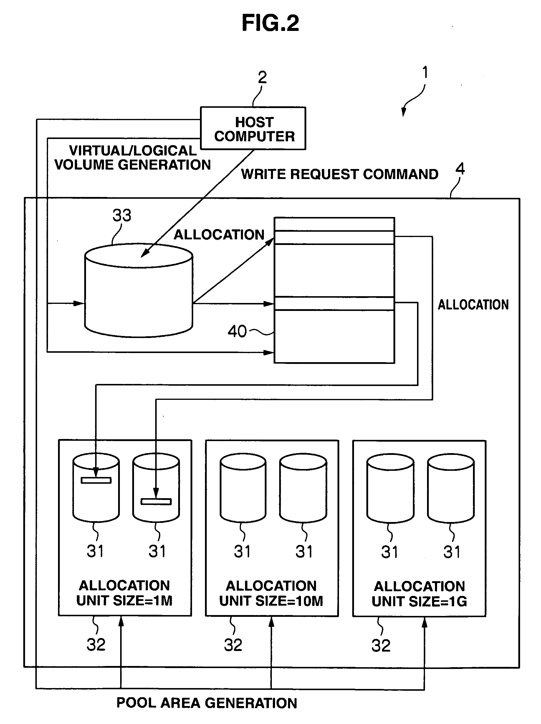
[0010] Accordingly, it is possible to effectively prevent storage area(s) from being allocated to data sent from the host computer, in units of allocation too large or too small relative to that data size, and allocate a storage area of an appropriate allocation unit size to that data.
[0012] Accordingly, it is possible to effectively prevent storage area(s) from being allocated to data sent from the host computer, in units of allocation too large or too small relative to that data size, and allocate a storage area of an appropriate allocation unit size to that data.
[0013] According to the present invention, by generating a plurality of pool areas, each composed from a storage area; setting for each of the plurality of pool areas, an allocation unit size for allocating a storage area from within the storage area provided by the pool area to the virtual / logical volume; selecting, when data to be stored in the storage area is sent from the host computer, one pool area from among the plurality of pool areas in accordance with the size of the sent data; and allocating a storage area from within the storage area provided by that selected pool area to the virtual / logical volume, it is possible to effectively prevent storage area(s) from being allocated to data sent from the host computer, in units of allocation too large or too small relative to that data size, and allocate a storage area of an appropriate allocation unit size to that data. As a result, a storage apparatus and a storage area allocation method that can greatly improve storage area operation efficiency can be achieved.

Problems solved by technology

So, if the fixed allocation unit size for the storage area for storing data sent from the host computer is large, that large portion of the storage area will be allocated even when a small piece of data is sent from the host computer, resulting in lower storage area operation efficiency.
On the other hand, in the storage apparatus disclosed by JP Patent Laid-Open Publication No. 2003-015915, the fixed allocation unit size for the storage area for storing data sent from the host computer is small, it is necessary to increase the number of management bits for managing the storage area allocated, and huge memory capacity is required to maintain those management bits.

Method used


Image

  • Storage apparatus and storage area allocation method
  • Storage apparatus and storage area allocation method
  • Storage apparatus and storage area allocation method

Examples


first embodiment

(1) First Embodiment

(1-1) Storage System Configuration According to a First Embodiment

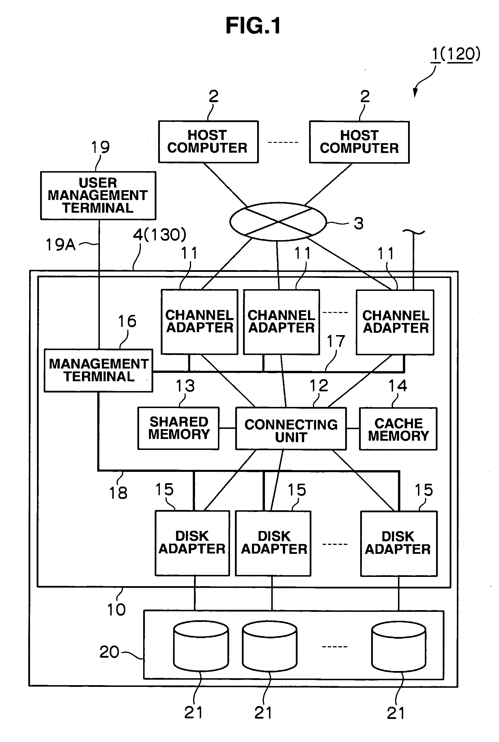
[0034]FIG. 1 shows the configuration of a storage system 1 according to a first embodiment. The storage system 1 is configured to include a plurality of host computers 2 connected to a storage apparatus 4 via a network 3.

[0035] The host computers 2, each as a host system, are computer devices equipped with a CPU (Central Processing Unit), memory and other information processing resources, and they are configured to be, for example, personal computers, workstations, mainframe computers, or similar. Each host computer 2 has data input devices, such as a keyboard, switch, pointing device, or microphone (not shown in the drawing), and data output devices, such as a monitor display or speaker (not shown in the drawing).

[0036] The network 3 is configured to be, for example, a SAN (Storage Area Network), LAN (Local Area Network), internet, public line, dedicated line, or similar. Communication between ...

second embodiment

(2) Second Embodiment

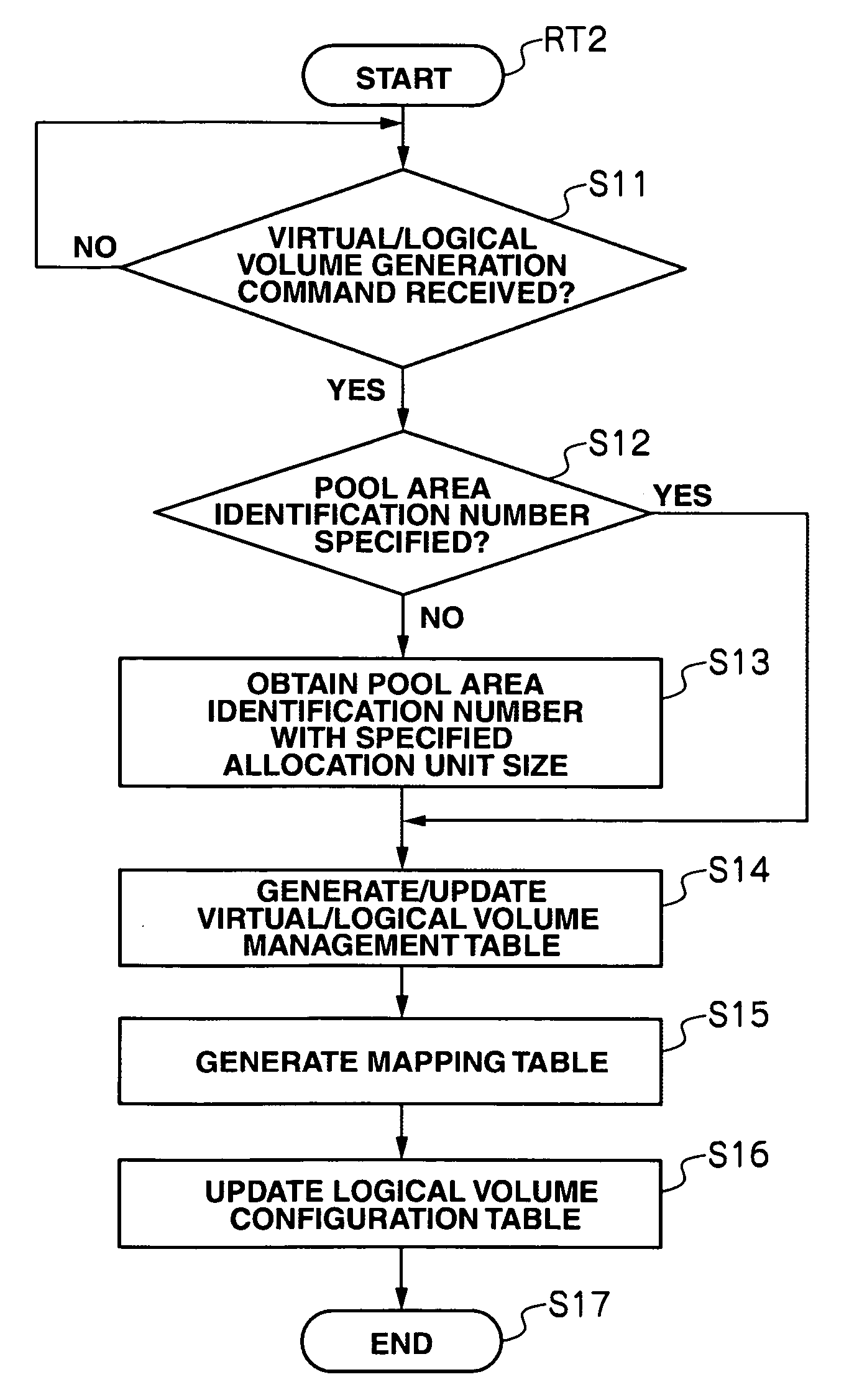
[0107] A storage system 120 according to a second embodiment has almost the same configuration as the storage system 1 according to the first embodiment, except that: it has a mapping table 40 with a different configuration; it includes a virtual / logical volume generation processing program 100 and command processing 110 with different content; and it has no virtual / logical volume management table 60.

[0108] Allocation processing for allocating a storage area to a virtual / logical volume in the storage apparatus 130 in the storage system 120 according to this embodiment will be explained below with reference to FIGS. 13 to 17. FIG. 13 is a schematic view briefly illustrating the content of that allocation processing.

[0109] In this embodiment, the storage apparatus 130 generates a plurality of pool areas 32 for holding physical / logical volumes 31, and sets, for each pool area 32, an allocation unit size for allocating a storage area from within the storage area p...


PUM


Abstract

A storage apparatus is provided with a storage area for storing data sent from a host computer, and a virtual / logical volume to which a dynamically variable storage area is allocated from within the storage area, the volume being provided to the host computer, and this storage apparatus is configured to include: a pool area generation unit for generating a plurality of pool areas composed from the storage area; a setting unit for setting, for each of the plurality of pool areas generated by the pool area generation unit, an allocation unit size for allocating a storage area from within the storage area provided by the pool area to the virtual / logical volume; a selecting unit for selecting, when data to be stored in the storage area is sent from the host computer, a pool area from among the plurality of pool areas having the allocation unit size set by the setting unit, in accordance with the size of the sent data; and an allocation unit for allocating a storage area from within the storage area provided by the pool area selected by the selecting unit to the virtual / logical volume.

Description

CROSS-REFERENCES TO RELATED APPLICATIONS [0001] This application relates to and claims priority from Japanese Patent Application No. 2006-092236, filed on Mar. 29, 2006, the entire disclosure of which is incorporated herein by reference. BACKGROUND OF THE INVENTION [0002] The present invention is suited for use in a storage apparatus with a virtual / logical volume to which a dynamically variable storage area is allocated, the volume being provided to a host computer. [0003] In recent years, storage apparatuses providing a host computer with storage areas for storing data have been able to include quite a large number of large-capacity disk drives, and the storage apparatus capacity has been expanding. This type of storage apparatus is operated so that: a disk array configured based on RAID (Redundant Array of Independent Disks) is generated from several disk devices; a plurality of so generated physical storage resources is then collected to make a physical / logical volume; and a stor...

Claims


Application Information

Patent Timeline
IPC IPC(8): G06F12/00
CPCG06F3/0608G06F3/0631G06F12/023G06F3/067G06F3/0644
Inventor KATO, TOMOYUKIYAMAGAMI, KENJI
Owner HITACHI LTD
Learn More