Mounting method of passive component

a passive component and mounting method technology, applied in the direction of printed circuit manufacturing, printed circuit aspects, final product manufacturing, etc., can solve the problems of uneven pulling force of melted solder on the two ends of the passive component, uneven amount of solder paste on the contact pad in the present surface mount technology, and uneven amount of solder paste on the contact pad. , to achieve the effect of easing the yield rate and reducing the loss of products

Inactive Publication Date: 2007-10-11
ADVANCED SEMICON ENG INC
View PDF12 Cites 9 Cited by
  • Summary
  • Abstract
  • Description
  • Claims
  • Application Information

AI Technical Summary

Benefits of technology

[0010]The invention is also directed to a mounting method of a passive component for solving the tombstone problem caused by uneven pulling force that the melted solder applies to the two ends of the passive component, for easing the yield rate and for reducing the product loss.
[0011]The invention is further directed to a mounting method of a passive component for fixing the passive component, so that the passive component is not misaligned because of the swaying of the passive component or the flowing of the solder paste in the reflowing process.

Problems solved by technology

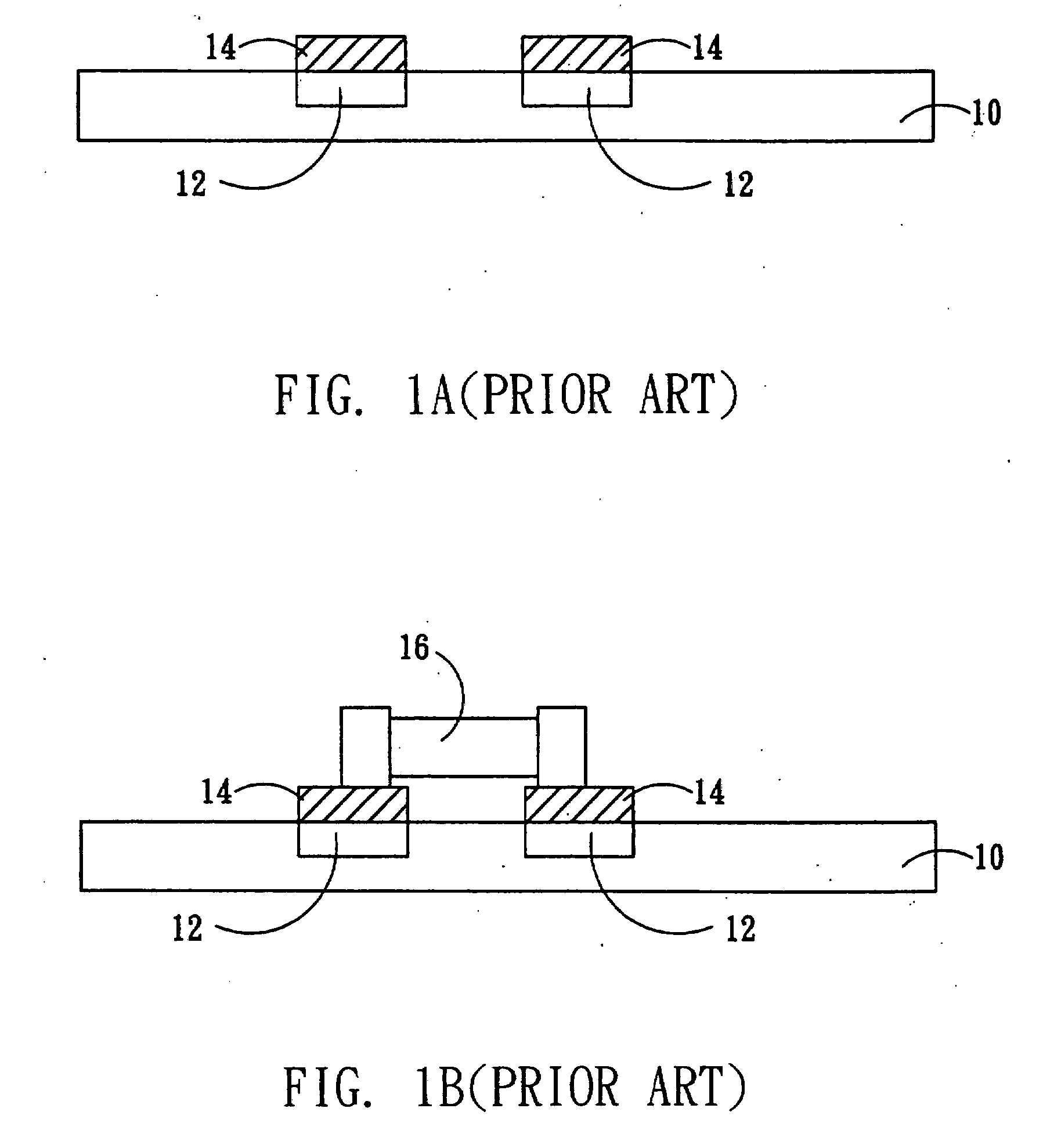
However, the amount of the solder paste on each contact pad in the present surface mount technology is often slightly different due to the inaccuracy of the manufacturing process.
For example, the size of each opening of the stencil is not always the same, and the stencil and the substrate may not be positioned accurately.
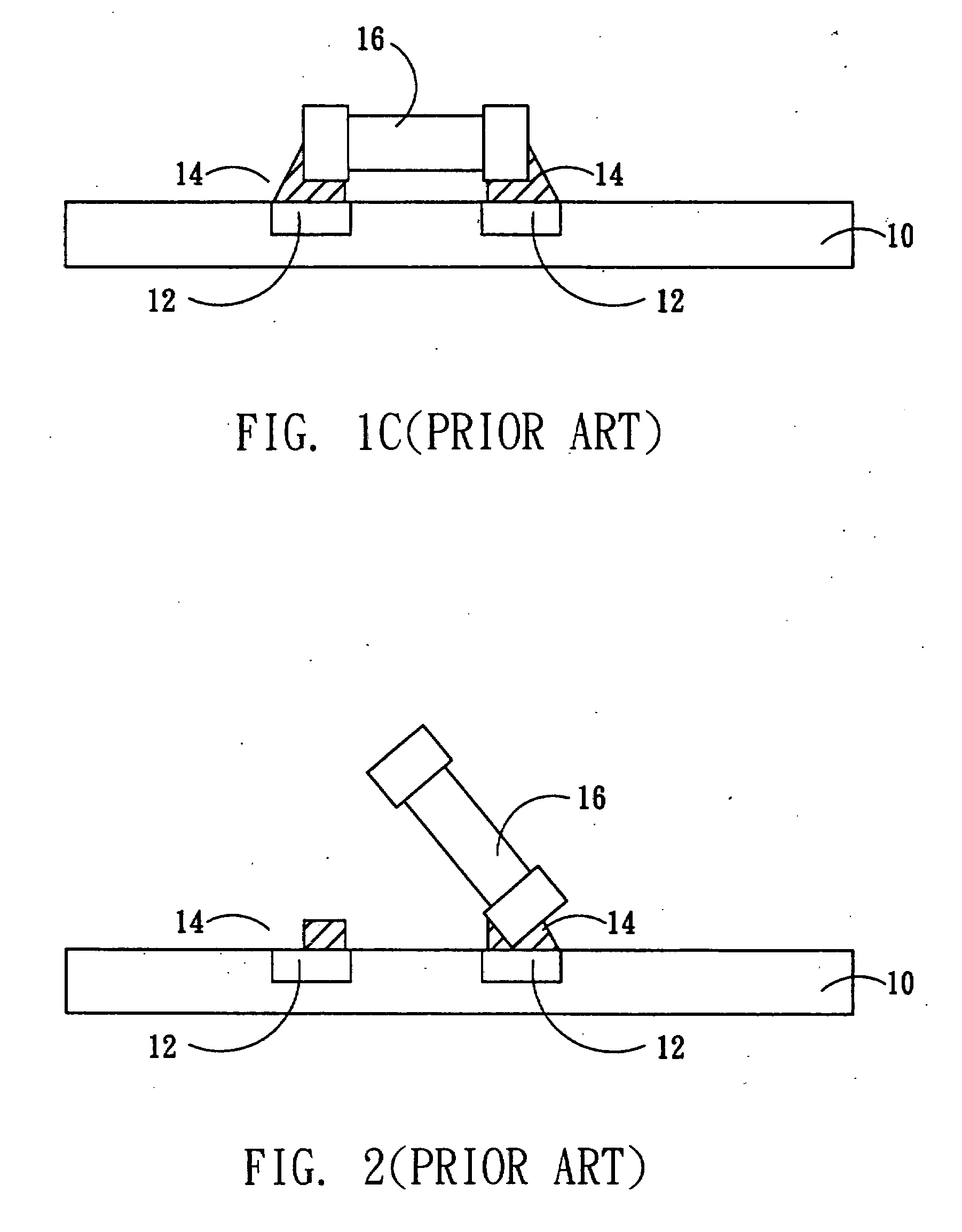
As a result, the pulling force that the melted solder applies to the two ends of the passive component is uneven in the reflowing process.
Or, the uneven pulling force may be caused when the passive component is misaligned on the contact pads.
When the pulling forces applied to the two ends of the passive component are not equivalent, the passive component is not positioned accurately.
However, as the electronic products become more compact and light-weight, all the components become smaller accordingly.
The conventional surface mounting method fails, and the yield rate is decreased.

Method used


Image

  • Mounting method of passive component
  • Mounting method of passive component
  • Mounting method of passive component

Examples


Embodiment Construction

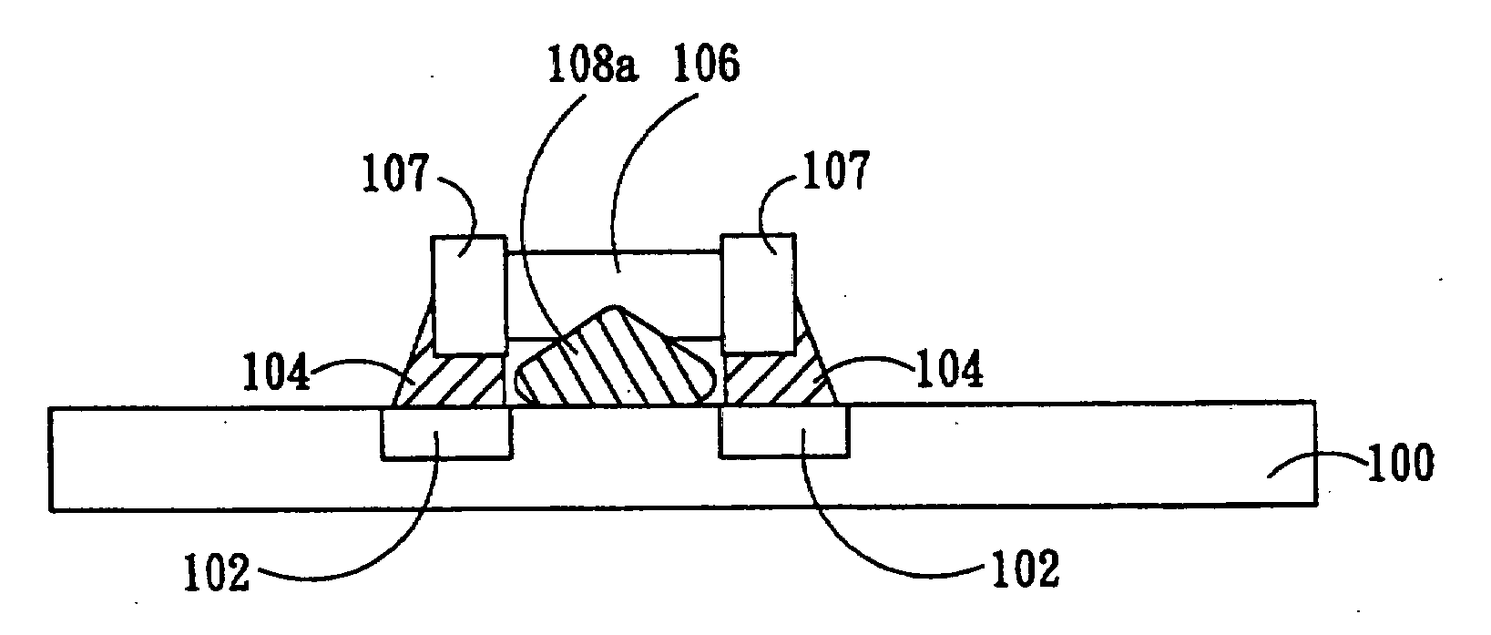
[0018]A preferred embodiment is described as follow to illustrate the present invention. However, the present invention can be applied to other embodiments in addition to the following one. In other words, the present invention is not limited to the provided embodiment. The scope of the present invention is to be determined according to the claims. Furthermore, when the component or structure in the drawings is described as a single component or structure, the present invention is not limited thereto. When the limitation of the number of the component is not emphasized in the following description, several components or structures can be applied under the spirit of the present invention. Moreover, different parts of each component in the drawings do not reflect the real dimensions. Some dimensions compared to others may be amplified or simplified in order to describe the present invention more clearly. The prior art used in the present invention is only mentioned briefly for illustr...


PUM

PropertyMeasurementUnit
melting temperatureaaaaaaaaaa
temperatureaaaaaaaaaa

Abstract

The present invention relates to a mounting method of passive component, and particularly relates to a mounting method of a small-size passive component. A passive component partially covered by an adhesive material is provided. Before the adhesive layer is melted, the adhesive material is melted and then solidified to form a fixing structure between the passive component and a substrate for fixing the passive component on the substrate. Therefore, the tombstone problem caused by uneven pulling force that the melted solder applies to the two ends of the passive component is effectively solved. The yield rate is increased, and the product loss is reduced.

Description

[0001]This application claims the benefit of Taiwan application Serial No. 95112388, filed Apr. 7, 2006, the subject matter of which is incorporated herein by reference.BACKGROUND OF THE INVENTION[0002]1. Field of the Invention[0003]The invention relates in general to a mounting method of a passive component, and more particularly to a mounting method of a passive component for solving the tombstone problem of the passive component caused by uneven pulling force that the melted solder applies to the two ends of the passive component.[0004]2. Description of the Related Art[0005]In the present package manufacturing process or the assembly process, the passive component is mounted alone or together with other components on the substrate or circuit board according to the demand. The surface mount technology (SMT) is the most common mounting method nowadays because of the advantages including fast manufacturing speed, high precision and high repeatability.[0006]Please referring to FIGS. ...

Claims


Application Information

Patent Timeline
Patent Type & Authority Applications(United States)
IPC IPC(8): H05K3/30
CPCH05K3/305H05K3/3442H05K3/3494H05K2201/10636Y10T29/4913H05K2203/1476Y10T29/49144Y10T29/49117H05K2201/10984Y02P70/50
Inventor LIN, WEN-SHINWANG, WEI-CHIH
Owner ADVANCED SEMICON ENG INC
Why Eureka
Try Eureka