Cooling system for a gas turbine, compressor guide blade and method for cooling a gas turbine

Inactive Publication Date: 2007-10-11
SIEMENS AG
View PDF5 Cites 19 Cited by
  • Summary
  • Abstract
  • Description
  • Claims
  • Application Information

AI Technical Summary

Benefits of technology

[0022] The cooling method according to the invention may in this case be carried out both during the operation of the gas turbine and after operation during a cooling phase for the more rapid cooling of the rotor. This immediately affords two advantages: during operation, the cooling of the cooling air can be adapted to the instantaneous operating or load state of the gas turbine, and, during a cooling phase carried out aft

Problems solved by technology

It has proved a disadvantage, as regards the first variant, that the tube passing through the diffuser obstructs the flow in the diffuser.
The second variant has the disadvantage that the liquid has to be transferred to the rotating system, but this is not trivial and entails

Method used


Image

  • Cooling system for a gas turbine, compressor guide blade and method for cooling a gas turbine
  • Cooling system for a gas turbine, compressor guide blade and method for cooling a gas turbine
  • Cooling system for a gas turbine, compressor guide blade and method for cooling a gas turbine

Examples


Embodiment Construction

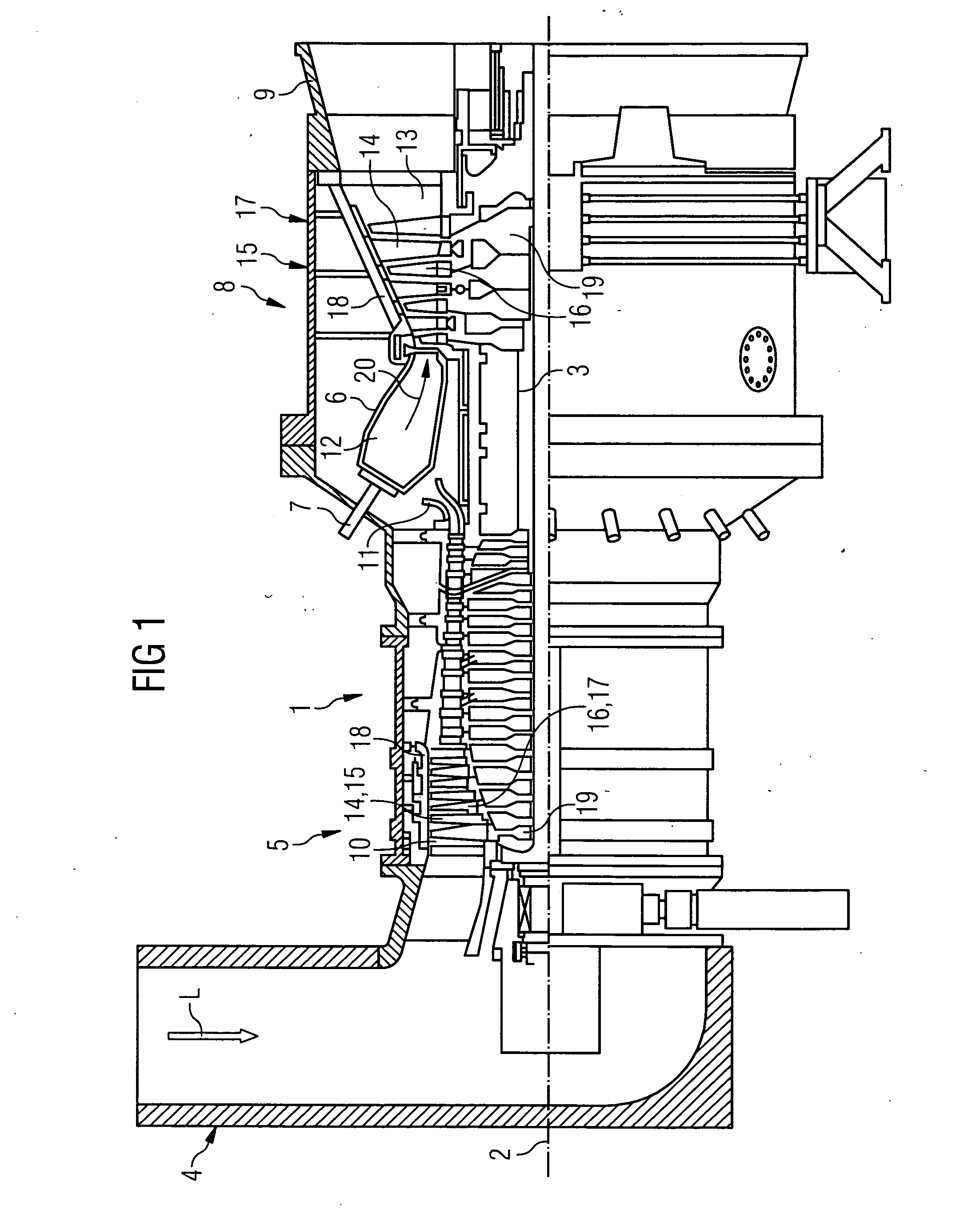
[0027]FIG. 1 shows a gas turbine 1 in a longitudinal part section. It has, inside it, a rotor 3 which is rotationally mounted about an axial rotation 2 which is designated as a turbine rotor. An intake casing 4, a compressor 5, a torus-like annular combustion chamber 6 with a plurality of annularly arranged burners 7, a turbine unit 8 and an exhaust gas casing 9 succeed one another along the rotor 3.

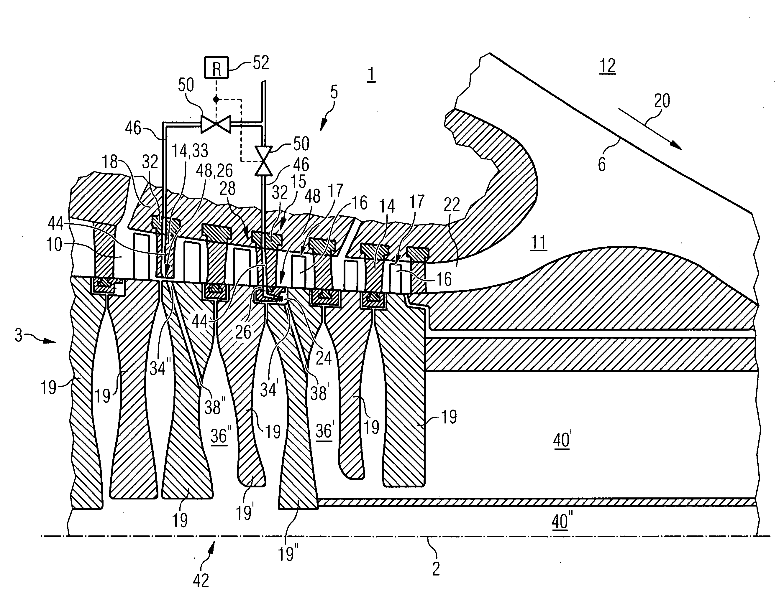
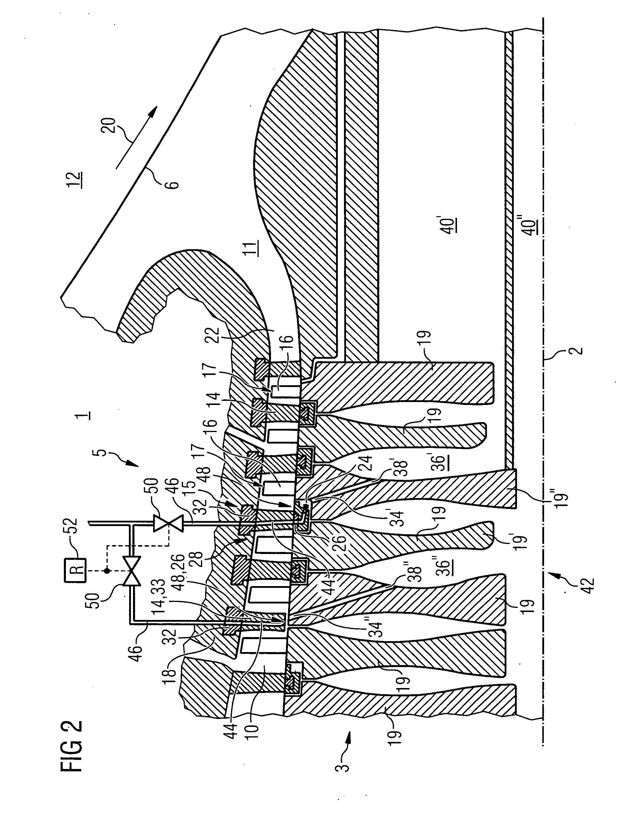
[0028] In the compressor 5, an annular compressor duct 10 is provided, which narrows in cross section in the direction of the annular combustion chamber 6. At the exit, on the combustion-chamber side, of the compressor 5, a diffuser 11 is arranged which is flow-connected to the annular combustion chamber 6. The annular combustion chamber 6 forms a combustion space 12 for a mixture consisting of a fuel and of compressed air. A hot-gas duct 13 is flow-connected to the combustion space 12, the hot-gas duct 13 being followed by the exhaust gas casing 9.

[0029] Blade rings are arranged in ea...


PUM


Abstract

The invention proposes a cooling system (42) for a gas turbine (1), with an annular duct extending axially in the compressor (5). In the annular duct, a ring (15) of compressor guide blades (14, 28, 33) and a ring (17) of moving blades (16) fastened to a rotor disk (19) of the rotor (3) are provided, with at least one cooling-air extraction point (34), arranged on the rotor (3), for diverting a cooling-air stream into a cooling-duct system arranged in the rotor (3), and with a turbine unit (8), in which, when the gas turbine (1) is in operation, components subjected to thermal stress by a hot gas (20) can be cooled by the divertible cooling-air stream, and also with a feed line (46) for feeding a liquid (45) into the cooling-air stream. In order to make it possible to feed a liquid into the cooling-air stream simply and cost-effectively, the invention proposes that the feed line (46) extend with a subduct (44) through at least one of the compressor guide blades (28, 33) of the ring (15), and the orifice (48, 49) for the outlet of the liquid (45) be connected in the region of the cooling-air extraction point (34).

Description

CROSS REFERENCE TO RELATED APPLICATION [0001] This application claims priority of the European application 04022590.6 EP filed Sep. 22, 2004, which is incorporated by reference herein in its entirety. FIELD OF THE INVENTION [0002] The invention relates to a cooling system for a gas turbine, with an annular duct, extending axially along a rotor, of a compressor, in which at least one ring of compressor guide blades fastened fixedly in terms of rotation and at least one ring of moving blades fastened to a rotor disk of the rotor are provided, which blades have in each case a securable blade root on which a blade profile and, following the latter, a blade head are formed, with at least one cooling-air extraction point, arranged on the rotor, for diverting a cooling-air stream into a cooling-duct system arranged in the rotor, and with a turbine unit, in which, when the gas turbine is in operation, components subjected to thermal stress by a hot gas can be cooled by the divertible coolin...

Claims


Application Information

Patent Timeline
IPC IPC(8): F02C6/08
CPCF01D5/185F01D5/186F02C7/185F02C7/18F01D9/041
Inventor VOSBERG, VOLKER
Owner SIEMENS AG
Why Eureka
Try Eureka