Control system for control subject having combustion unit and control system for plant having boiler

a control system and control subject technology, applied in the direction of instruments, specific gravity measurement, nuclear elements, etc., can solve the problems of unsupervised learning method, change in combustion characteristics and heat transfer characteristics of the plant, and affect the external environment, so as to reduce the amount of generated toxic substances and reduce the time period

Active Publication Date: 2007-10-11
HITACHI LTD
View PDF12 Cites 38 Cited by
  • Summary
  • Abstract
  • Description
  • Claims
  • Application Information

AI Technical Summary

Benefits of technology

[0032]The present invention includes the above-described units and can properly control exhaust gas components automatically even when fuel compositions (properties) are changed, it is possible to decrease a amount of generated toxic substances such as NOx and CO in the exhaust gas.
[0033]Since the present invention includes the units to attain the above-described second object, the plant can be controlled based on a reinforcement learning method by using results of numerical value analysis from trial running of the plant. Accordingly, it is possible to reduce a time period in which the control system is introduced.

Problems solved by technology

In order to construct a control system by using a supervised learning function, successful models of teacher data may be prepared, and thus an unsupervised learning method also has been proposed.
A plant control system including a combustion apparatus encounters with problems in which combustion characteristics and heat transfer characteristics of the plant are changed when fuel properties are not constant like coal fuels or when coal types are changed.
If NOx and CO and the like are increased, there is a possibility that external environment will be affected and a load on an exhaust gas treatment system will be increased.
However, the above-described documents fail to describe a method which takes an influence to combustion gas compositions into consideration.
Also, a combustion phenomenon is a complicated compound phenomenon of fuel and fluid of air (gas) and heat transfer and combustion reaction so that to control behaviors of the combustion phenomenon is a difficult problem.
In particular, it has been difficult to introduce a suitable operation method for controlling the change of exhaust gas compositions relative to the change of fuel properties.
Even when the aforementioned reinforcement learning theory is used, a learning period of a long time is required to learn an operation method for controlling a wide variety of fuel properties in a trial and error fashion.
At the same time, there is a possibility that gas properties will be degraded during the learning period.
Accordingly, problems arise, in which quality of products is lowered to increase a loss during such period of time.
In addition, although it is considered that a bad influence will be exerted upon the environment by the fluctuations of properties of wastes from the plant when the plant has been run in a trial and error fashion, a method of constructing a model effective for these problems is not taken into consideration.
According to the Patent Document 3, while mesh of calculation should be made smaller in order to increase calculation accuracy, a large-sized apparatus such as a boiler needs a vehemently large calculation amount and the running condition also changes continuously so that a calculation time is increased, thereby making it difficult to construct a model within a practical time period.
As described above, while the reinforcement learning method is the effective method for controlling the plant in which a control method may not be formulated in advance, if data are accumulated by trial running of the plant in order to construct a model that may need a longer time, a desired control efficiency may not be obtained during a trial running period.

Method used


Image

  • Control system for control subject having combustion unit and control system for plant having boiler
  • Control system for control subject having combustion unit and control system for plant having boiler
  • Control system for control subject having combustion unit and control system for plant having boiler

Examples


first embodiment

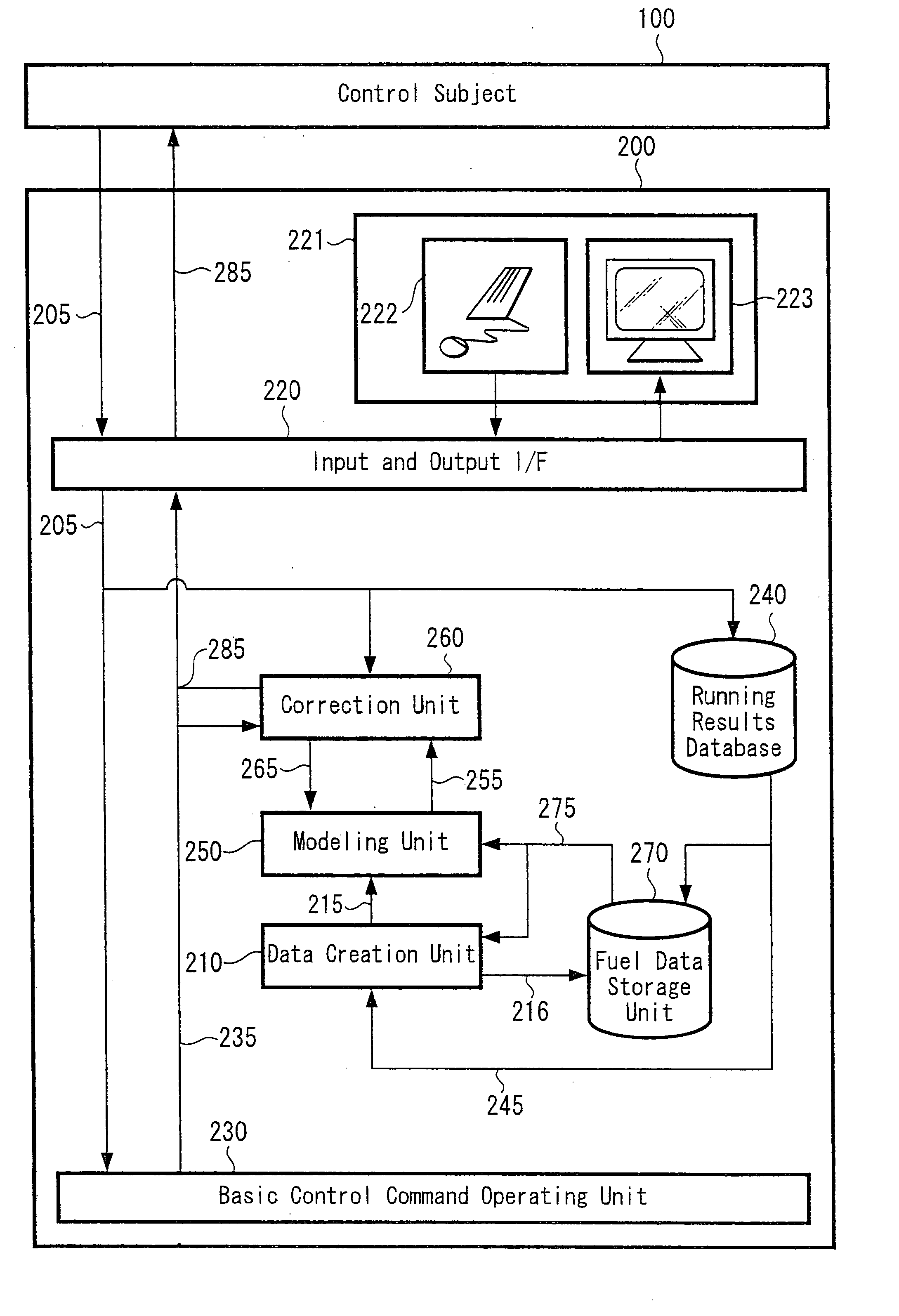
[0056]The embodiments of the present invention will be described below with reference to drawings. FIG. 1 of an accompanying drawing shows the present invention. As shown in FIG. 1, a control system 200 according to the present invention receives process value measurement information 205 from a plant 100 indicating a control subject, carries out operation pre-programmed within the control system 200. An operation command signal (control signal) 285 is transmitted to the plant 100 using the resulting measurement information 205. The plant 100 controls a condition of the plant by driving actuators such as gates of valves and gates of dampers in accordance with the received operation command signal 285.

[0057]This embodiment is an example in which the present invention is applied to combustion control of a thermal power plant. According to the embodiment of the present invention, in particular, the example in which the present invention is applied to control functions to decrease NOx co...

second embodiment

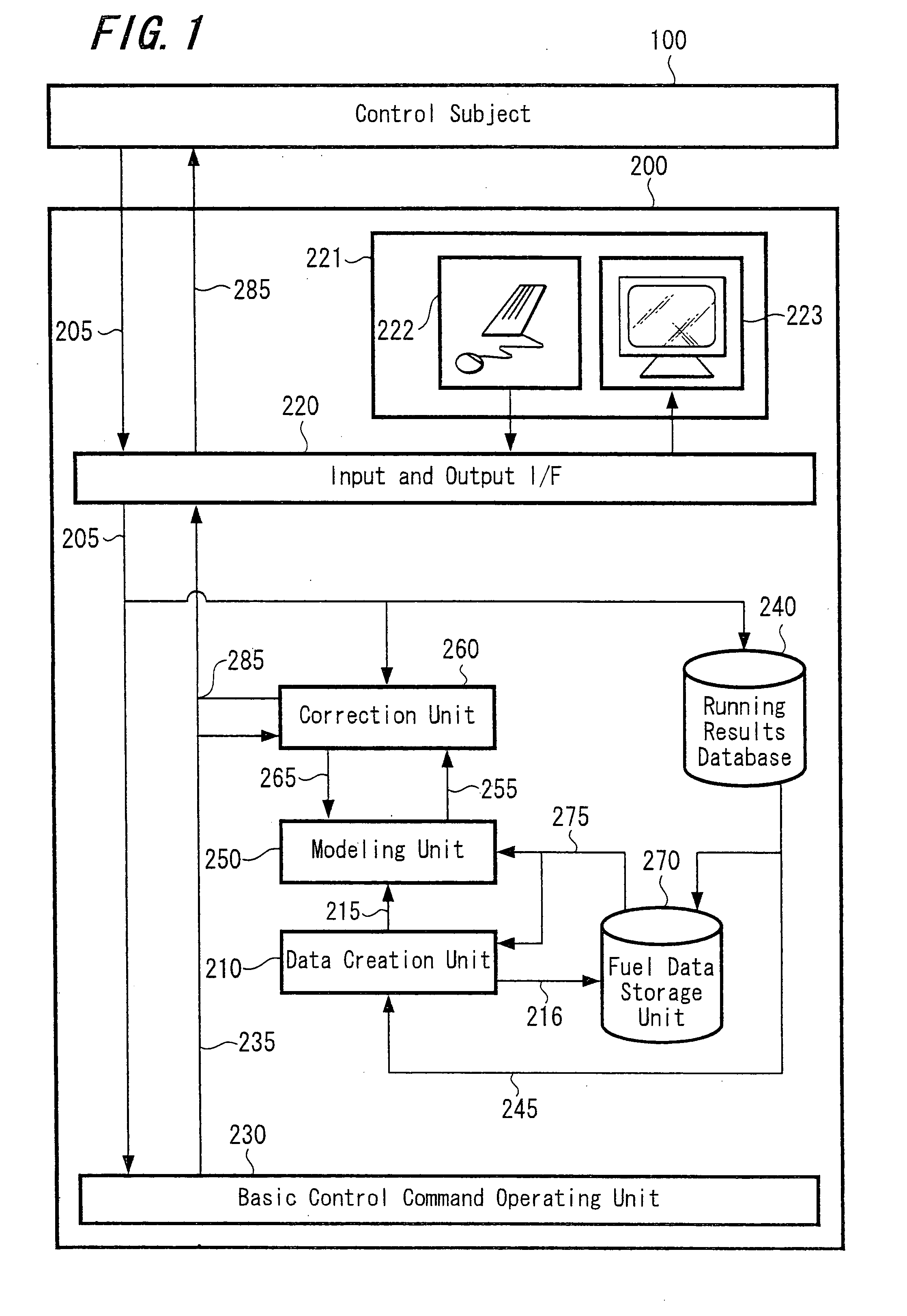
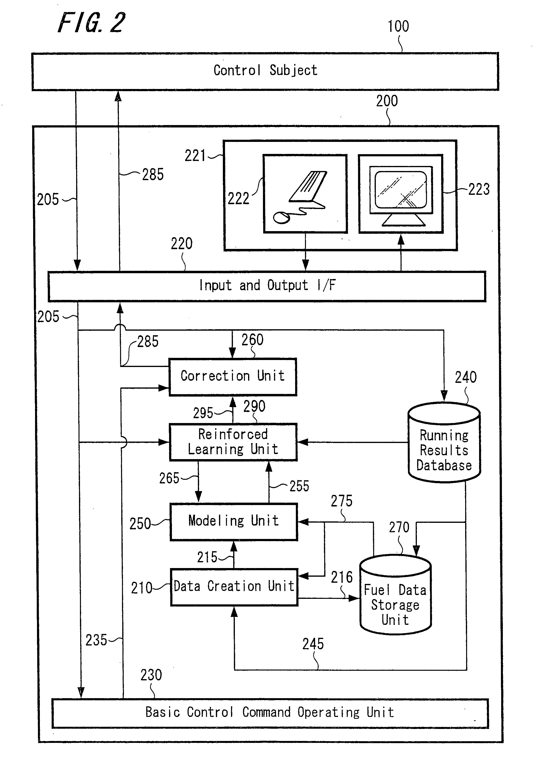
[0119]Next, the present invention will be described with reference to FIG. 2.

[0120]The second embodiment differs from the aforementioned first embodiment in learning an operation method of decreasing NOx and CO by using the reinforcement learning unit 290.

[0121]The reinforcement learning unit 290 has a function to learn a proper operation method corresponding to the plant state based on a reinforcement learning theory by using running data accumulated in the running results database 240.

[0122]Detailed explanations of the reinforcement learning theory have been described in “Reinforcement Learning” (translated jointly by Sadayoshi Mikami and Masaaki Minagawa, published by Morikita Publishing CO., Ltd., Dec. 20, 2000) and hence only a concept of reinforcement learning will be described.

[0123]FIG. 9 shows a control concept based on a reinforcement learning theory. As shown in FIG. 9, a control system 610 outputs an operation command 630 to the control subject 600. The control subject 6...

third embodiment

[0146]Next, the present invention will be described with reference to FIG. 3.

[0147]The third embodiment is different from the second embodiment that the third embodiment includes a state evaluation unit 300 and data set switching unit 310. The state evaluation unit 300 monitors model error that is a deviation between the calculated value of the model created by the modeling unit 250 and the corresponding running results data 205.

[0148]Processing procedures of the state evaluation unit 300 and the data set switching unit 310 will be described with reference to FIG. 12.

[0149]Referring to FIG. 12, a set value of an allowable value relative to model error is read at a step 600.

[0150]At a step 610, the running results data 205 and the calculated value obtained by inputting the model of the operation amount result value are read.

[0151]At a step 620, a deviation (model error) between the running results data 205 read at the step 610 and the model calculated value 255 in the corresponding o...


PUM

PropertyMeasurementUnit
distanceaaaaaaaaaa
distancesaaaaaaaaaa
flow rateaaaaaaaaaa

Abstract

A control system includes a basic control command operating unit, a fuel data storage unit, a running results database for storing past running results values of a control subject, a data creating unit configured to calculate a distance between data of the past running results values and the data sets and determining data set in which a distance between data becomes minimum, a modeling unit configured to model a relationship between operation parameters of a combustion apparatus and components in combustion gas of the combustion apparatus by using the data set determined by the data creating unit and a correcting unit for calculating combustion apparatus operation parameters with which components having a better condition than that of the components in a current gas are provided by using a model of the modeling unit and correcting operation command values of the basic control command operating unit by calculated operation parameters.

Description

CROSS REFERENCES TO RELATED APPLICATIONS[0001]The present invention contains subject matter related to Japanese Patent Application JP 2006-086131 filed in the Japanese Patent Office on Mar. 27, 2006, Japanese Patent Application JP 2006-098519 filed in the Japanese Patent Office on Mar. 31, 2006 and the entire contents of which being incorporated herein by reference.BACKGROUND OF THE INVENTION[0002]The present invention relates to a control system for a control subject having a combustion unit.[0003]A control logic based on PID (proportional-integral-derivative) control has long been the mainstream in the field of plant control. A large number of technologies capable of flexibly deal with characteristics of a plant have been proposed using a supervised learning function represented by a neural network.[0004]In order to construct a control system by using a supervised learning function, successful models of teacher data may be prepared, and thus an unsupervised learning method also ha...

Claims


Application Information

Patent Timeline
Patent Type & Authority Applications(United States)
IPC IPC(8): G01N7/00
CPCF23N3/002F23N5/00F23N2023/48F23N2023/36F23N2021/10F23N2221/10F23N2223/36F23N2223/48G05B13/0265
Inventor YAMADA, AKIHIROKANADA, MASAKISEKIAI, TAKAAKIHAYASHI, YOSHIHARUKUSUMI, NAOHIROFUKAI, MASAYUKISHIMIZU, SATORU
Owner HITACHI LTD
Why Eureka
Try Eureka