
Fired heater and flue gas tunnel therefor

a flue gas tunnel and heater technology, applied in the field of fired heaters and flue gas tunnels therefor, can solve the problems of significant shortcomings, high construction cost, time-consuming and labor-intensive, etc., and achieve the effect of reducing the number of slintels or tile covers, and reducing the cost of installation, maintenance and repair

Inactive Publication Date: 2007-10-11
INTEGRATED SERVICE
View PDF27 Cites 10 Cited by
  • Summary
  • Abstract
  • Description
  • Claims
  • Application Information

AI Technical Summary

Benefits of technology

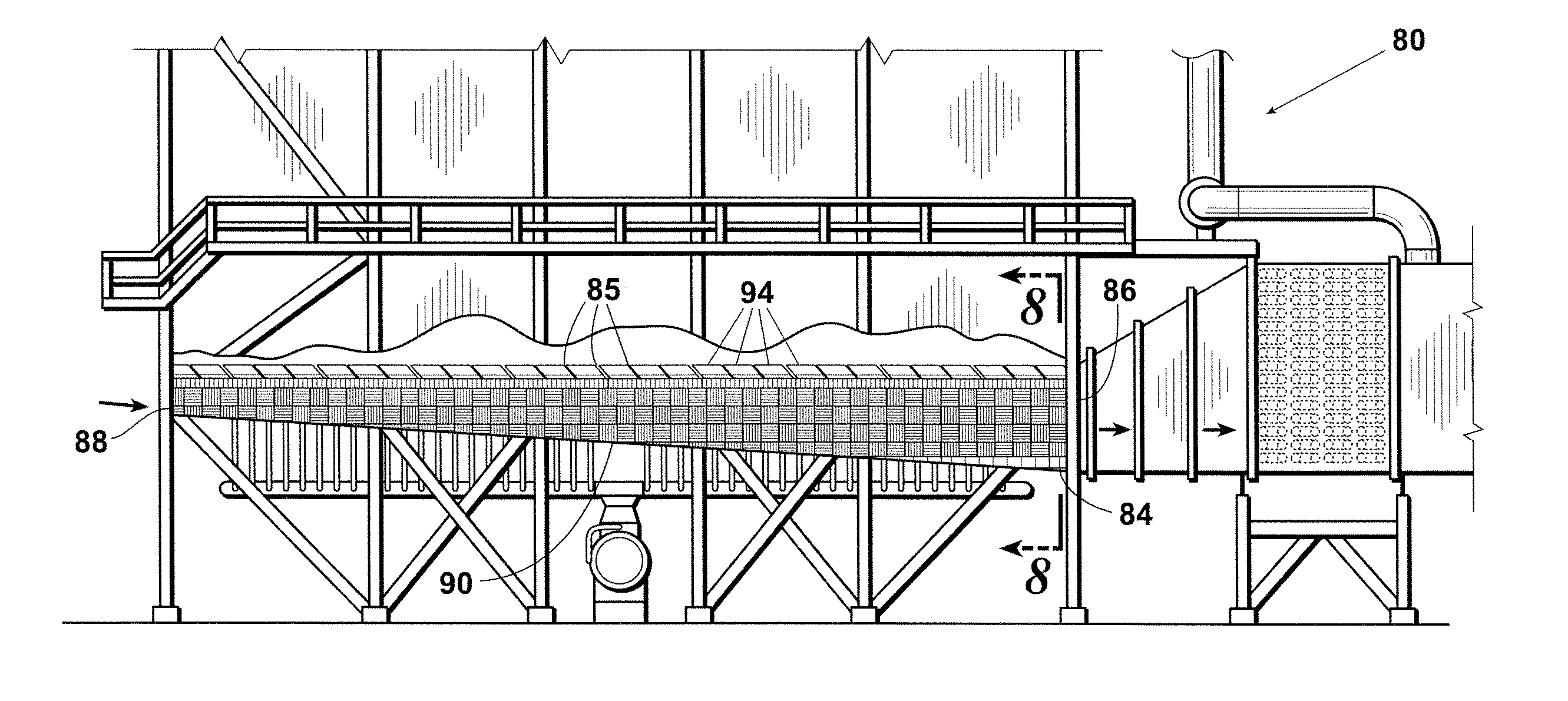
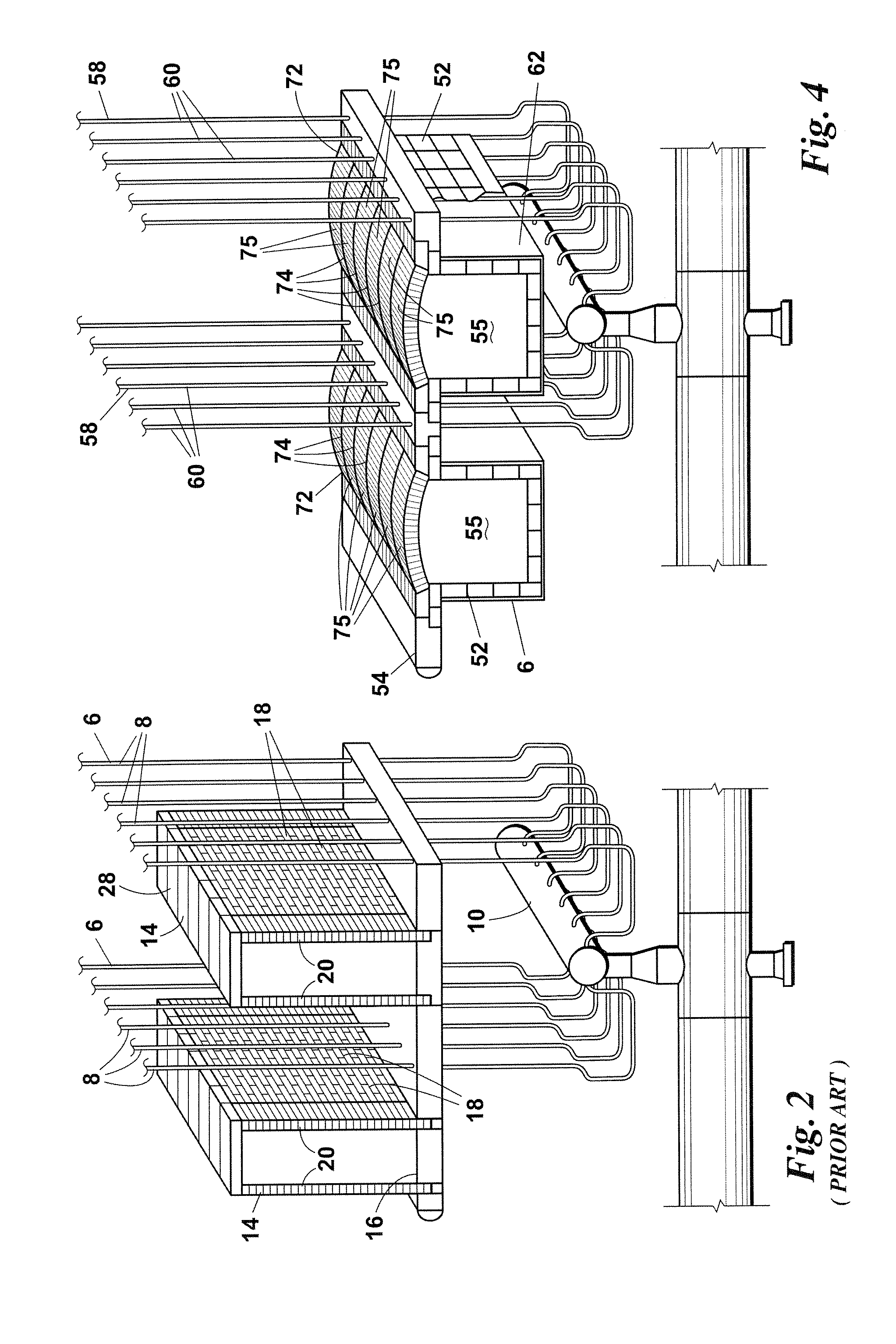
[0008] The present invention provides several benefits and advantages over the flue gas tunnels heretofore used in the art. Examples of the benefits and advantages provided by the present invention include: eliminating the presence of and the need to construct the vertical brick side walls of the prior art tunnels within the radiant firebox; the ability to construct the flue gas tunnels offsite and install refractory linings therein prior to shipment; significantly reducing the weight of the flue gas tunnels; allowing the addition of convenient man way doors to the firebox for workers and materials; reducing the time required to erect scaffolding within the firebox for inspection and repairs; greatly increasing the available work space and maneuverability within the firebox; significantly reducing the structural support requirements and costs of the heater; and significantly improving the distribution and uniformity of the flue gas flow within the firebox and the flue gas tunnels.

Problems solved by technology

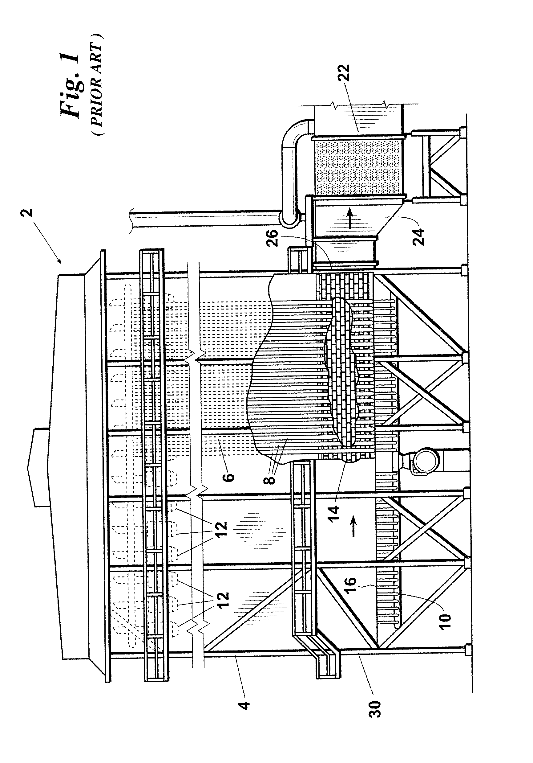
Unfortunately, the flue gas tunnel systems heretofore used in the art have significant shortcomings and are costly and time-consuming to install, maintain, and repair.
In addition, the construction process is very time consuming and difficult due to the extremely limited space and maneuverability within the firebox 4 between the tube rows 6.
In addition, the flat lintel or tile covers 28 of the prior art tunnels 14 undergo significant fatigue when exposed to the extreme temperature conditions within the firebox over time and tend to break.
This results in the formation of cracks and holes in the covers 28 which further degrade the flue gas flow distribution and uniformity within the firebox 4 and within the tunnels 14.

Method used


Image

  • Fired heater and flue gas tunnel therefor
  • Fired heater and flue gas tunnel therefor
  • Fired heater and flue gas tunnel therefor

Examples


example

[0030] Simulations were run using computer models of (a) a top-fired reformer heater utilizing the prior art flue gas tunnel system depicted in FIGS. 1 and 2 and (b) a top-fired reformer heater employing the inventive flue gas tunnel system illustrated in FIGS. 7-9. The simulations employed: a standard high Reynolds number turbulence model; a discrete ordinates (S4 for ordinate set) method for computing thermal radiation heat transfer; and the weighted sum of gray gases method to compute the gas absorption coefficient assuming natural gas combustion at 10% excess air. Meshes were prepared using the advanced meshing module of Prostar 3.26. The simulations each employed between 1.1 and 1.8 million cells and each required over 60 CPU-hours of processing time.

[0031] The models simulate flue gas flow, convection heat transfer from the flue gas to the heater coils, and radiative heat transfer to the coils from the flue gas and refractory surfaces. The flue gas flow is specified as six fe...


PUM


Abstract

An improved fired heater having one or more flue gas tunnels installed in the firebox floor such that at least most of the lateral cross section of the flue gas tunnel is below the firebox floor.

Description

BACKGROUND OF THE INVENTION [0001] Hydrogen reformer units are commonly used in the petrochemical industry to produce hydrogen gas from methane and steam. One common hydrogen reformer process employs a prior art reformer heater 2 of the type depicted in FIGS. 1 and 2. The prior art heater 2 comprises: a square or rectangular radiant firebox 4; a plurality of rows 6 of process tubes 8 which extend through the radiant firebox 4 and are filled with a catalyst; a collection manifold system 10 which receives the hot process product from the lower ends of the process tubes 8; a plurality of rows of downwardly firing burners 12 installed in the top of the radiant firebox 4 between the rows 6 of tubes 8; a plurality of flue gas tunnels 14 which are constructed within the firebox 4 and extend along the floor 16 of the firebox 4 between each adjacent pair of tube rows 8 and between the outermost tube rows 8 and the side walls of the firebox 4; a plurality of inlet openings 18 through the vert...

Claims


Application Information

Patent Timeline
IPC IPC(8): F22B9/08
CPCF22B13/04F22B9/08
Inventor TACKER, WALTER RAY
Owner INTEGRATED SERVICE
Learn More