

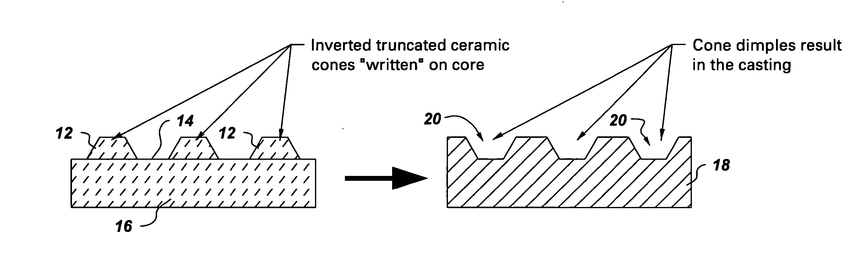
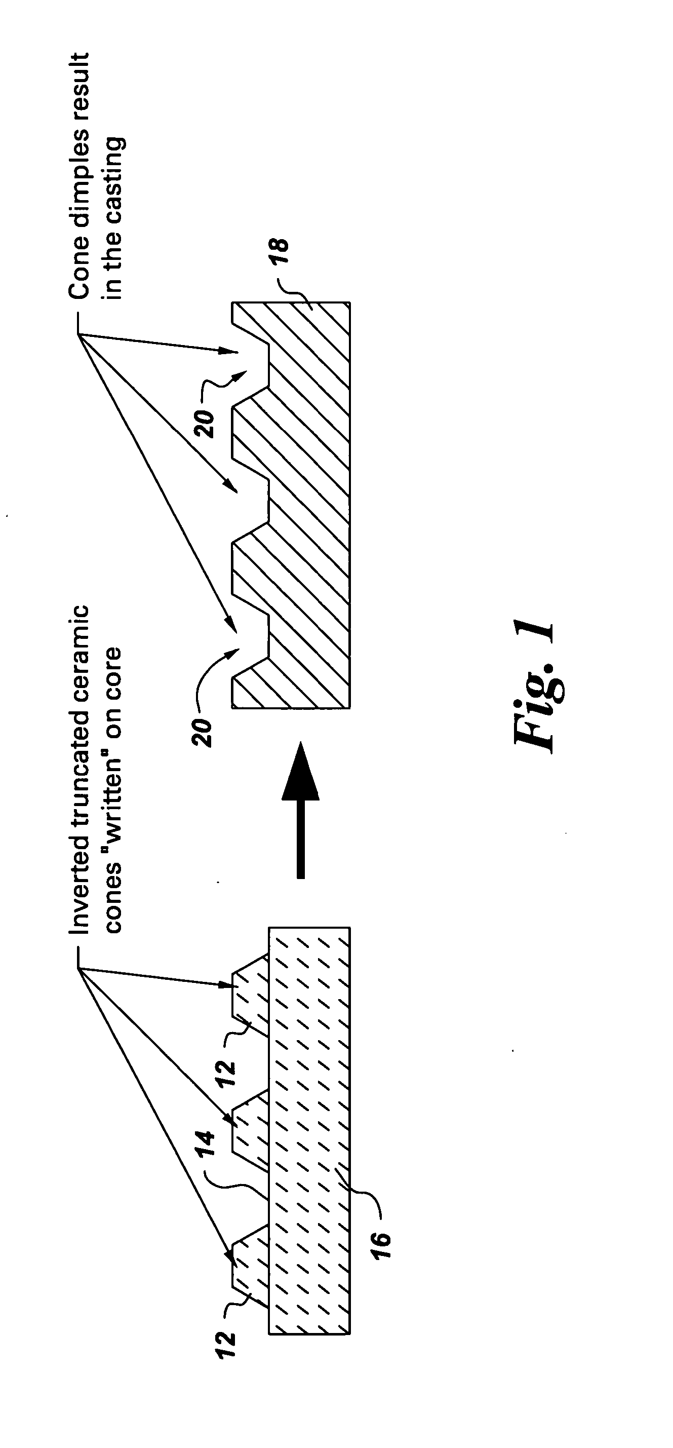
Method of forming concavities in the surface of a metal component, and related processes and articles
a technology of concavity and metal components, applied in the field of metal components, can solve the problems of increasing the operating temperature of the turbine component, increasing the cooling effectiveness, and causing the failure of the turbine element and destroying the engin
- Summary
- Abstract
- Description
- Claims
- Application Information
AI Technical Summary
Benefits of technology
Problems solved by technology
Method used
Image

Examples
examples
[0075] The following example is provided for illustration, and should not be considered to be any type of limitation on the scope of the present invention.
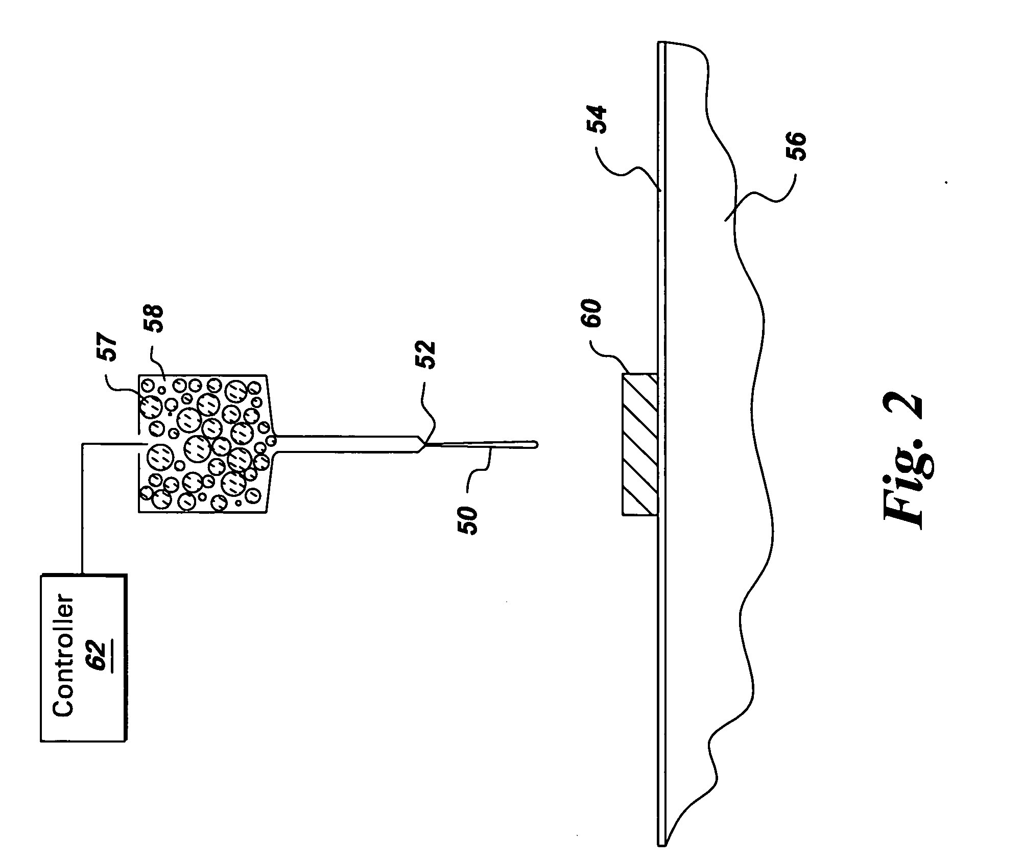
[0076] A Micropen™ device (400 Series), from Ohmcraft, Inc., Honeoye Falls, N.Y.) was used in this example. The pen size was 10 mils (0.25 mm) outer diameter×7 mils (0.18 mm) inner diameter.
[0077] A section of electronic-grade alumina was used as the workpiece / substrate in this example. Its dimensions were about 2 inches×1⅜ inch (5.1 cm×3.5 cm), with a thickness of about 1 mm. The workpiece was positioned on a platform in the device which is movable along X and Y axes via computer-control. The workpiece was held in place by a vacuum.
[0078] The deposition material was alumina / magnesium oxide (10% by weight MgO, based on Al2O3 and MgO combined). It was prepared by dry-mixing powders of the two oxides, and then adding solvent (terpineol), with additional mixing. (The solvent included a small amount of cellulose binder). The amount...
PUM
| Property | Measurement | Unit |
|---|---|---|
| Shape | aaaaa | aaaaa |
| Metallic bond | aaaaa | aaaaa |
| Refractory | aaaaa | aaaaa |
Abstract
Description
Claims
Application Information