PDC cutter for high compressive strength and highly abrasive formations

Inactive Publication Date: 2007-10-11
VAREL INT IND
View PDF15 Cites 61 Cited by
  • Summary
  • Abstract
  • Description
  • Claims
  • Application Information

AI Technical Summary

Benefits of technology

[0038] The invented configuration of PDC cutter seeks to increase drilling efficiency by the following: The shape of the PDC cutter requires less weight on bit than conventional PDC cutters, lessening wear and cracking due to frictional heating. It is composed of preferred PDC materials to increase the cutters resistance to heat. The shape of the cutter is optim

Problems solved by technology

While the concepts of leaching cutters and using elliptical shaped cutters have improved the performance of PD

Method used


Image

  • PDC cutter for high compressive strength and highly abrasive formations
  • PDC cutter for high compressive strength and highly abrasive formations
  • PDC cutter for high compressive strength and highly abrasive formations

Examples


Embodiment Construction

[0045] Generally speaking, the present invention relates to the use of a leached PDC cutter which has an elliptical cutter geometry. This cutter has a unique diamond layer geometry and configuration that minimizes the risk of de-lamination, and delays the onset of wear, but as wear progresses, allows the cutter to “lip” thus preserving the cutter's rock shearing capability.

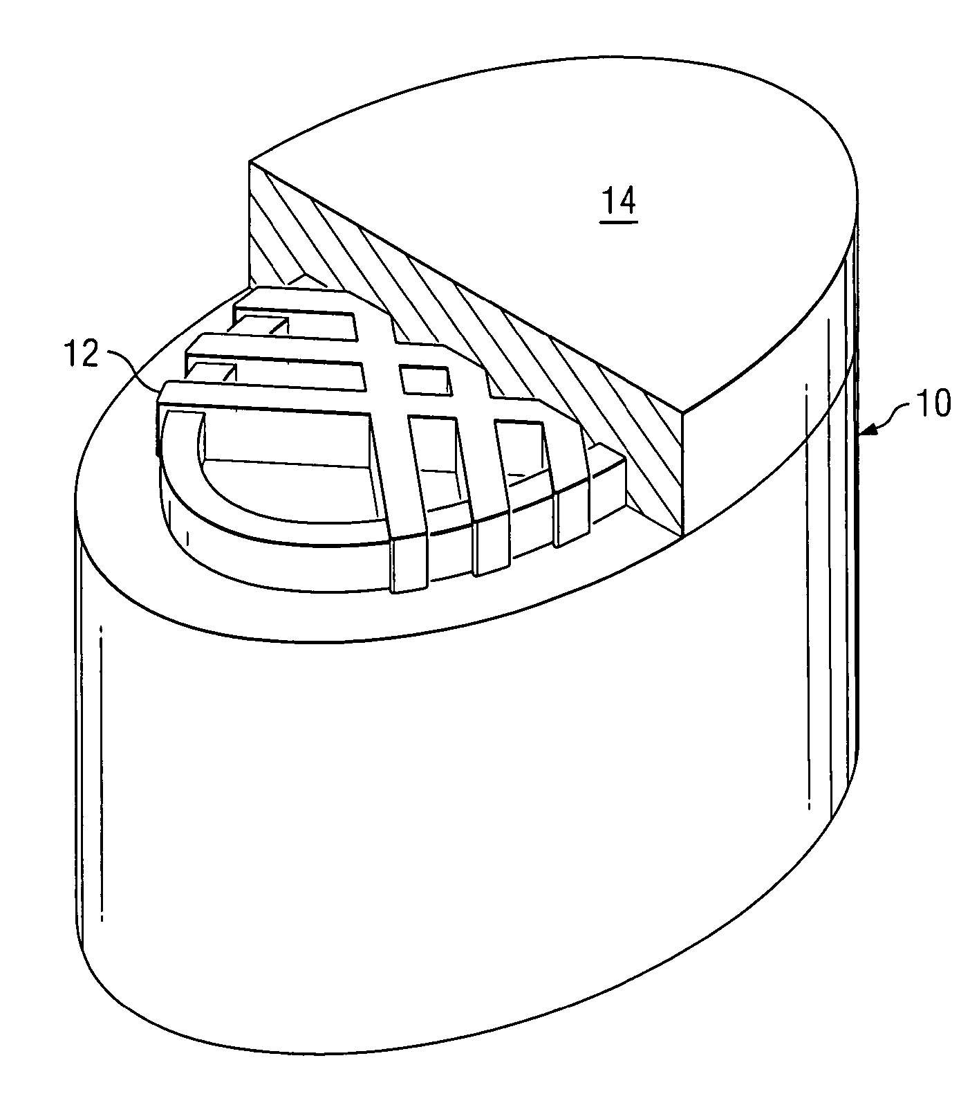
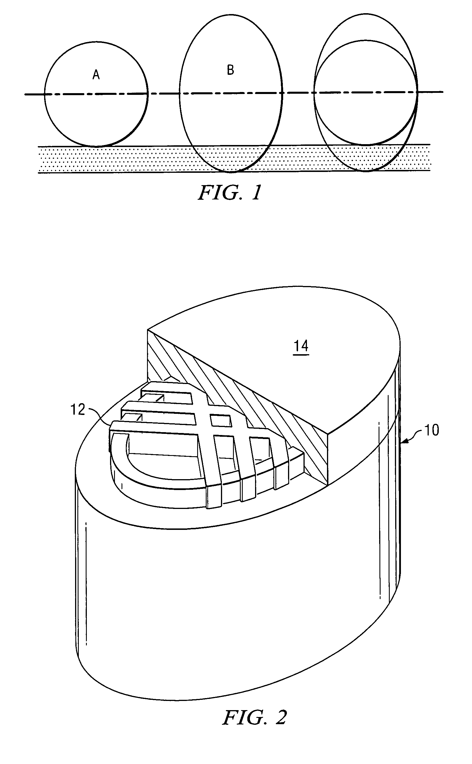
[0046] As shown in FIG. 2, diamond volume is maximized around the edge of the cutter. Protrusions from the tungsten carbide portion 10 of the cutter form a pattern 12 (in this exemplary illustration, cross-hatched) which allows for the diamond 14 volume to be larger about the perimeter edge, and smaller / shallower in the center region, while providing surfaces for the diamond layer (table) to bond to the underlying tungsten carbide substrate. Again, the cutter has an elliptical shape and the diamond table has been subjected to leaching. When the cutter is unworn, this thicker diamond resists wear at the cutting ti...


PUM


Abstract

A PDC cutter utilizes the combination of an elliptical shape with higher thermal resistance obtained through leaching to provide a cutter which is more effective than a cutter using either concept alone. The PDC cutter includes a tungsten carbide portion with protrusions extending from a surface thereof in a pattern. The diamond volume is mounted to the surface wherein the protrusions allow for the diamond volume to be larger about a perimeter edge of the cutter and smaller/shallower in a center region of the cutter. The protrusions providing surfaces for the diamond layer (table) to bond to the underlying tungsten carbide portion. With this configuration, diamond volume is maximized around the edge of the cutter.

Description

CROSS REFERENCE TO RELATED APPLICATION [0001] The present application claims the benefit of U.S. Provisional Application for Patent No. 60 / 751,835 filed Dec. 20, 2005, the disclosure of which is hereby incorporated by reference.BACKGROUND OF THE INVENTION [0002] 1. Technical Field of the Invention [0003] The present invention relates to a PDC cutter used for drilling boreholes into the earth. [0004] 2. Description of Related Art [0005] Drilling high compressive strength rocks that are highly abrasive has always been a challenge for PDC cutters. When a rock has a high compressive strength, high force is required for the cutter to penetrate the rock. High cutting forces cause problems. When the high cutting forces are transmitted to the drill string, drilling problems occur. For example, the drill string can buckle or bow causing unwanted deviation of the well. High forces cause problems within the cutter. The higher forces cause more frictional heating. The heating causes rapid wear ...

Claims


Application Information

Patent Timeline
IPC IPC(8): E21B10/00
CPCE21B10/573
Inventor CUILLIER, BRUNODOURFAYE, ALFAZAZIMAURSTAD, CARYREESE, MIKETHIGPEN, MIKEPALASCHENKO, YURI A.
Owner VAREL INT IND
Why Eureka
Try Eureka