

Detecting apparatus, and detecting method
a detection apparatus and information technology, applied in the direction of optical radiation measurement, instruments, material analysis, etc., can solve the problems of difficult to appropriately regulate the interaction area between the thz wave and the sample, the location of the dripped and the inability to accurately drip the sample on the transmission path
- Summary
- Abstract
- Description
- Claims
- Application Information
AI Technical Summary
Benefits of technology
Problems solved by technology
Method used
Image

Examples
first embodiment
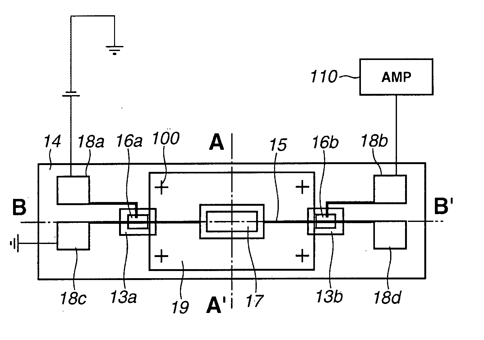
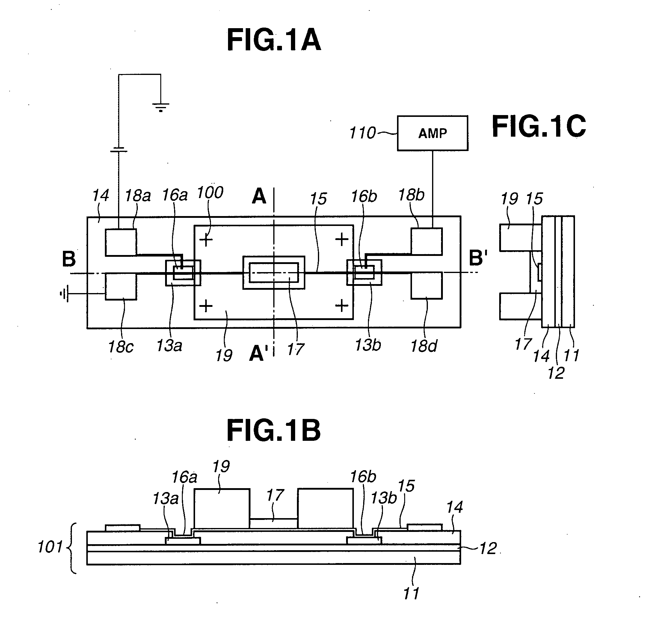
[0073] The embodiments will be described in more detail with reference to FIGS. 1A to 1C. In the detecting apparatus of the first embodiment, a ground of the transmission path is a metal plane 12 formed on a substrate 11 by vacuum evaporation or the like. The substrate 11 is, for example, a silicon substrate. The metal plane 12 is made of, for example, 500 Å thin titanium and 3000 Å thin gold. On the metal plane 12, two LT (low-temperature)-GaAs layers 13a and 13b are formed by epitaxial lift-off or the like. A dielectric layer 14 relatively transparent for THz wave is formed on the LT-GaAs layers 13a and 13b. The dielectric layer 14 is made of, for example, BCB (benzocyclobutene). The thickness of the dielectric layer 14 is 5 microns, for example. A portion of the dielectric layer 14 is removed, and the LT-GaAs layers 13a and 13b are partly exposed. On the dielectric layer 14, a metal line (a signal line) 15 is formed extending with a width of about 5 microns to 10 microns, and a l...
second embodiment
[0099] Also in the second embodiment, the gap of the THz-wave supplying unit is illuminated with femtosecond (fsec) laser light to generate THz wave, and the THz wave is transmitted through the transmission path. After interaction with the sample in the porous material 42, the THz wave reaches the THz-wave detecting unit. Thus, the time-domain waveform and forth of the THz wave can be obtained.
[0100] In the second embodiment, the porous material 42 is in direct contact with the line 41, and no intervening substance, such as adhesive, exists therebetween. Reliable detection can be expected in this embodiment. Further, the polystyrene plates 43a and 43b extend along the two sides of the porous material 42 as described above. Accordingly, even when much liquid sample beyond the liquid holding capability of the porous material 42 is dripped, virtually no liquid sample spreads toward a direction leaving from the line 41. When the porous material 42 is an anisotropic porous material or fi...
third embodiment
[0102] Also in the third embodiment, the gap of the THz-wave supplying unit is illuminated with femtosecond (fsec) laser light to generate THz wave, and the THz wave is transmitted through the transmission path. After interaction with the sample in the porous material 52, the THz wave reaches the THz-wave detecting unit. Thus, the time-domain waveform of the THz wave can be obtained, for example.
[0103] A fourth embodiment of the present invention will be described referring to FIGS. 6A to 6C. In this embodiment, a hole is formed in the polystyrene plate 63 having a thickness of about 1 mm, and the porous material 62 with an outer size slightly larger than the hole is set covering the hole therewith, using bonding adhesive or the like. The polystyrene plate 63 is the non-infiltrative member of resin having a high transmissivity for THz wave. The size of the hole is about 0.4 mm*0.3 mm, and the size of the porous material 62 is 0.6 mm*0.4 mm, for example. Element 61 represents a metal...
PUM
 Abstract
Description
Claims
Application Information