Angle beam shear wave through-transmission ultrasonic testing apparatus and method

a technology of through-transmission and ultrasonic inspection, applied in the direction of instruments, specific gravity measurement, magnetic property measurement, etc., can solve the problems of introducing additional time and labor, limiting the access to the interior surface of the structure, and traditionally not being able to inspect internal defects of the structure using ultrasonic inspection, etc., to improve the resolution of three-dimensional defects, improve the depth measurement, and improve the effect of three-dimensional image generation

Inactive Publication Date: 2007-07-10
THE BOEING CO
View PDF13 Cites 77 Cited by
  • Summary
  • Abstract
  • Description
  • Claims
  • Application Information

AI Technical Summary

Benefits of technology

[0010]The present invention provides an improved apparatus and method for inspecting a structure using angle beam shear wave through-transmission ultrasonic signals. Embodiments of the present invention combine shear wave ultrasonic inspection methods and technologies with magnetically coupled inspection probe technologies to provide angle beam shear wave inspection devices that are portable, can be used for various applications, and provide inspection results in real-time, including three-dimensional imaging of internal features of a structure. Such devices can be used for high resolution defect detection in structures of varying shapes and sizes, including structures such as bondlines, weldlines, and lap joints and structures including such obstructions as vertical stiffeners, webbings, and walls that prevent or limit access to regions of the structure. Embodiments of systems, apparatus, and methods of the present invention can be used for inspection of structures during manufacture or in-service. Further, embodiments of the present invention provide new inspection capabilities for non-destructive inspection of large and small structures, structures with limited-access features, and complex features of structures.
[0011]Systems, apparatus, and methods of the present invention typically use magnetically coupled probes including respective sensing elements that are disposed at offset positions on opposing surfaces of a structure. Additionally, systems, apparatus, and methods of the present invention are capable of operating in array modes, thereby increasing inspection speed and efficiency while reducing cost.
[0012]For continuous scanning applications using magnetically coupled probes, only one probe need be driven due to magnetic coupling between the probes, or magnetic coupling between one probe and a magnetic coupling device connected to the other probe by a support element. Thus, methods, systems, and apparatus of the present invention are advantageously adapted to inspect structures in which one surface of the structure is relatively inaccessible or structures which are exceptionally large and are advantageously capable of angle beam shear wave through-transmission ultrasonic inspection. Also, embodiments of methods, systems, and apparatus of the present invention permit the probes to contact and ride along the respective surfaces of the structure, thereby reducing or eliminating the necessary sophistication of a motion control system that is typically required by conventional scanning systems to maintain the probes in a predefined orientation and predefined positions with respect to each other and at a predefined spacing from the respective surface of a structure undergoing inspection. Manual inspection is also capable using magnetically coupled angle beam shear wave through-transmission ultrasonic inspection probes in accordance with an embodiment of the present invention. Permitting the probes to contact and ride along the respective surfaces of the structure also may maintain alignment between the probes and / or the angle beam shear wave ultrasonic sensors of the probes. The probes may use contact members to support the probes against the respective surfaces of the structure. Contact with the surface permits accurate position measurement of the inspection device during continuous scanning, such as keeping an optical or positional encoder in physical and / or visual contact with the surface of the structure under inspection. Contact with the surface also permits the probes to disperse a couplant between the surface of the structure and the angle beam shear wave ultrasonic sensors.
[0019]According to yet another aspect of the present invention, a method, apparatus, and system may generate a three-dimensional image representation using pulse-echo ultrasonic inspection data in addition to angle beam shear wave through-transmission ultrasonic signal inspection data. Pulse-echo ultrasonic inspection data may be used to supplement the angle beam shear wave through-transmission ultrasonic signal inspection data. Although pulse-echo ultrasonic inspection has limitations as a complete inspection technique, pulse-echo ultrasonic inspection, such as using a far-side, receiving transducer, may be used to improve three-dimensional defect resolution. For example, distance data can be determined directly from a pulse-echo signal time-of-flight, thereby improving the depth measurement for a three-dimensional image representation. Similarly, variations in the amplitude of a pulse-echo inspection signal can provide information for reconstructing a defect. Pulse-echo inspection signal amplitude can be affected by variations in surface orientations of a defect. Facets of a defect that are more perpendicular to a pulse-echo signal will reflect a return signal with high amplitude. Facets of a defect that are more parallel to a pulse-echo signal will reflect a return signal with low amplitude. Thus, a method, apparatus, and system of the present invention may use pulse-echo distance and / or amplitude data to improve three-dimensional image generation.

Problems solved by technology

In the field, access to interior surfaces of the structure is often restricted, requiring disassembly of the structure, introducing additional time and labor.
For example, typical defects in composite sandwich structures, generally made of one or more layers of lightweight honeycomb or foam core material with composite or metal skins bonded to each side of the core, include disbonds which occur at the interfaces between the core and the skin or between the core and a buried septum.
Further, surface defects and discontinuities typically hide internal defects and discontinuities from traditional ultrasonic pulse echo methods.
However, it has traditionally not been feasible to inspect internal defects of a structure using ultrasonic inspection because of surface defects and features.
However, for through-transmission ultrasonic inspection, a semi-automated inspection system requires access to both sides or surfaces of a structure which, at least in some circumstances, will be problematic, if not impossible, particularly for semi-automated systems that use a fixed frame for control of automated scan heads.
Conventional automated scanning systems, such as the AUSS-X system, therefore require access to both sides or surfaces of a structure which, at least in some circumstances, will be problematic, if not impossible, particularly for very large or small structures.
Access to the structure to conduct inspection may be so limited that manual or automated inspection is not possible.
Furthermore, scanning systems inspect limited areas up to a few meters square.
Many parts, however, incorporate features, such as internal wall and protruding boss elements, which prevent use of conventional scanning methods.
Further, surface defects and discontinuities and structural elements of a part may limit the usefulness of conventional scanning methods.

Method used


Image

  • Angle beam shear wave through-transmission ultrasonic testing apparatus and method
  • Angle beam shear wave through-transmission ultrasonic testing apparatus and method
  • Angle beam shear wave through-transmission ultrasonic testing apparatus and method

Examples


Embodiment Construction

[0025]The present invention will be described more fully with reference to the accompanying drawings. Some, but not all, embodiments of the invention are shown. The invention may be embodied in many different forms and should not be construed as limited to the described embodiments. Like numbers and variables refer to like elements and parameters throughout the drawings.

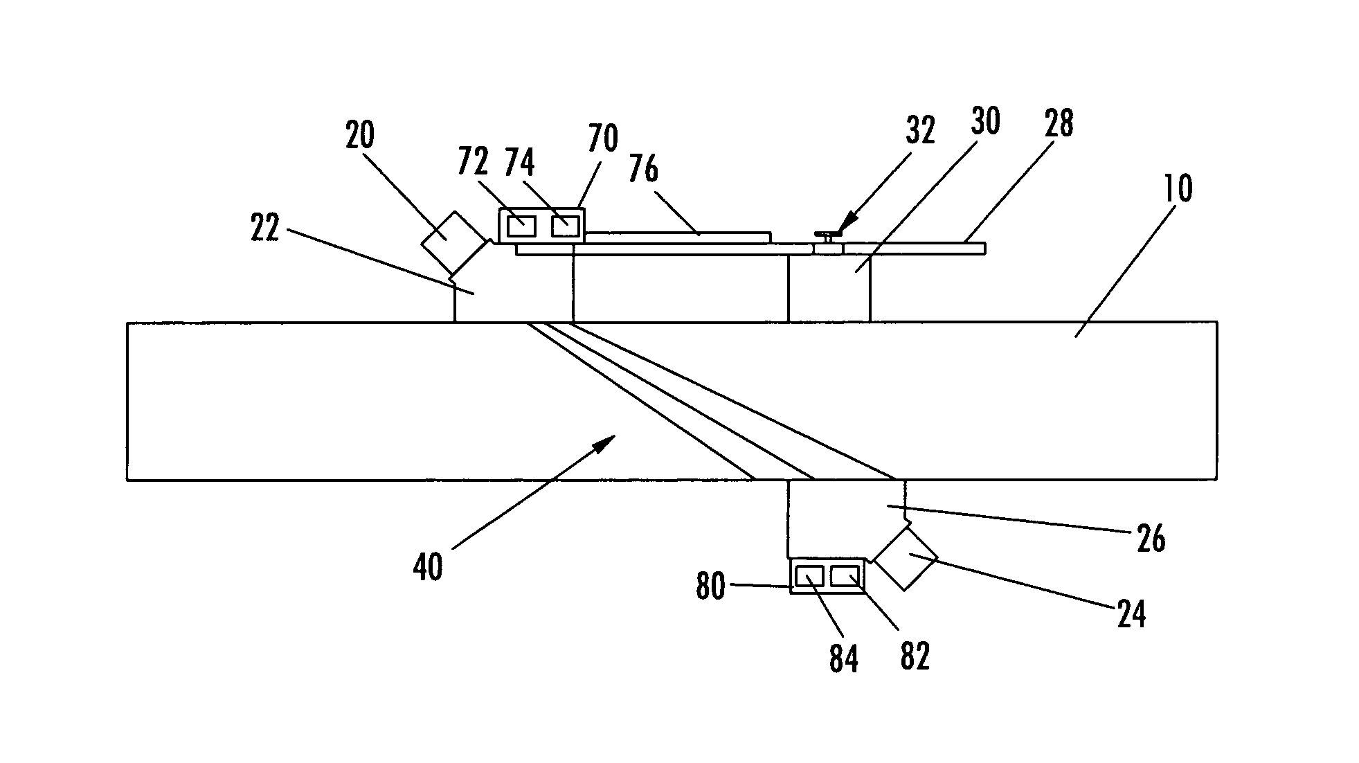
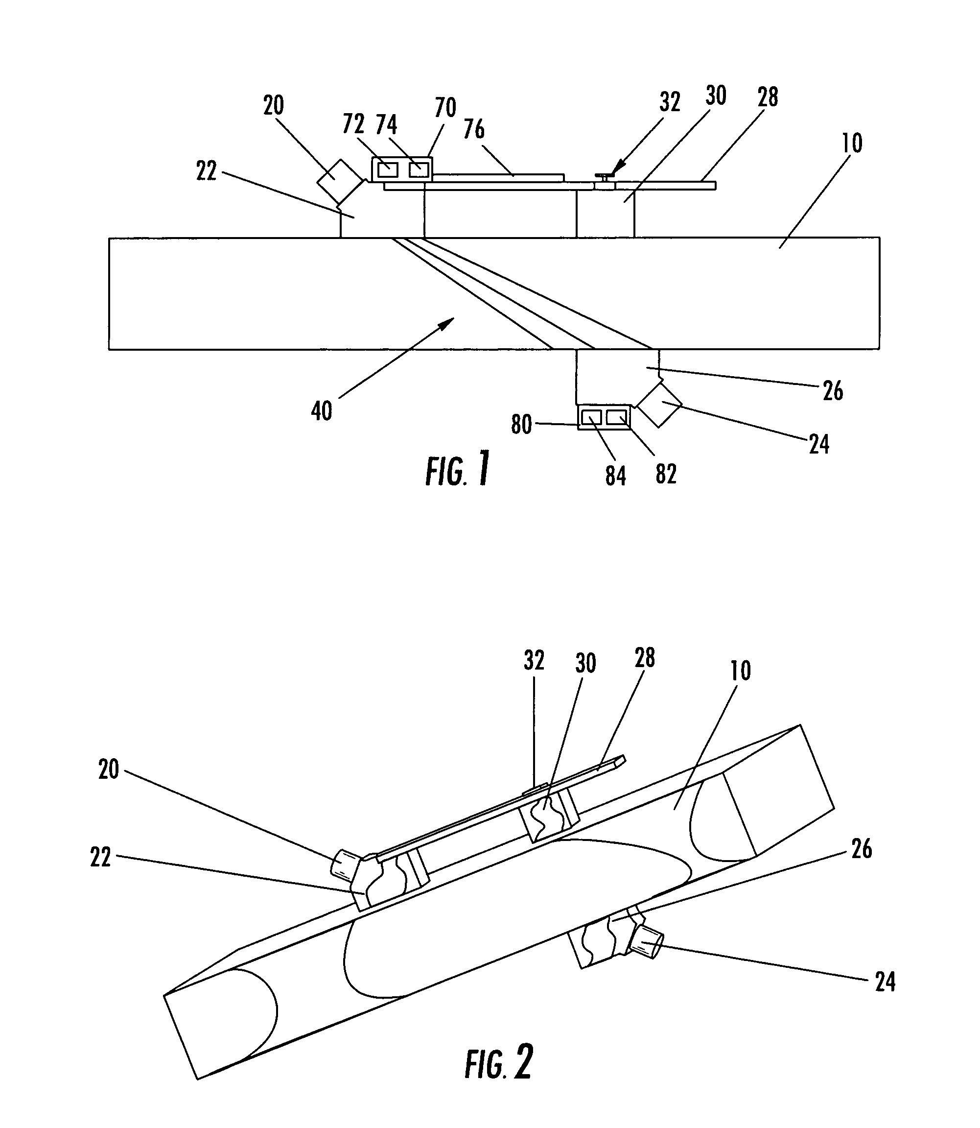
[0026]When angle beam shear wave transducers have typically been used for non-destructive inspection, a shear wave transducer bounces an ultrasonic signal at an angle off the back and / or end of a structure such that the signal is repeatedly reflected, and the same transducer catches the multiple-reflected signal or a different transducer catches the signal on the same side of the structure as the transmitting transducer. This method may be referred to as angle beam shear wave pitch-catch. The use of angle beam shear waves with multiple reflections may permit inspection of the inside of a structure behind a surface de...


PUM

PropertyMeasurementUnit
extraction anglesaaaaaaaaaa
insertion angleaaaaaaaaaa
angleaaaaaaaaaa

Abstract

Improved methods, systems, and apparatus for inspecting a structure using angle beam shear wave through-transmission ultrasonic signals involves positioning transducers at offset positions on opposing sides of the structure and permits inspection of the inside of the structure beneath surface defects and features. Magnetic coupling can be used for supporting a pair of leader-follower probes and defining offset positions between angle beam shear wave transducers carried by the probes. Inspection data can be collected for supporting real-time generation of three-dimensional image representations of the structure and of internal defects and features of the structure. Image generation and resolution using inspection data from angle beam shear wave ultrasonic signals can be supplemented using pulse-echo ultrasonic inspection data.

Description

CROSS-REFERENCE TO RELATED APPLICATIONS[0001]The contents of U.S. Pat. No. 6,722,202 and application Ser. No. 10 / 734,452, entitled “Ultrasonic Inspection Device for Inspecting Components at Preset Angles,” filed Dec. 12, 2003; application Ser. No. 10 / 752,890, entitled “Non-Destructive Inspection Device for Inspection Limited-Access Features of a Structure,” filed Jan. 7, 2004; application Ser. No. 10 / 943,088, entitled “Magnetically Attracted Inspecting Apparatus and Method Using a Ball Bearing,” filed Sep. 16, 2004; application Ser. No. 10 / 943,135, entitled “Magnetically Attracted Inspecting Apparatus and Method Using a Fluid Bearing,” filed Sep. 16, 2004; and application Ser. No. 11 / 045,861, entitled “X-Ray Laminography Inspection System and Method,” filed Jan. 28, 2005, are incorporated by reference.FIELD OF THE INVENTION[0002]The present invention relates generally to an apparatus and method for inspecting a structure and, more particularly, to an apparatus and method for non-des...

Claims


Application Information

Patent Timeline
Patent Type & Authority Patents(United States)
IPC IPC(8): G01N29/24
CPCG01N29/041G01N29/11G01N29/2481G01N29/2487G01N29/265G01N2291/0289G01N2291/0421G01N2291/0422G01N2291/0428G01N2291/044G01N2291/048G01N2291/056G01N2291/102
Inventor GEORGESON, GARY E.FOGARTY, MICHAEL D.
Owner THE BOEING CO
Why Eureka
Try Eureka