Adaptive DC to DC converter system

a converter system and dc technology, applied in the field of dc to dc converter systems, can solve the problems of loss of power transfer efficiency with high heat dissipation, large circuit area, complex design of switching voltage regulators, etc., and achieve the effect of maximizing conversion efficiency and minimizing switching power loss

a converter system and dc technology, applied in the field of dc to dc converter systems, can solve the problems of loss of power transfer efficiency with high heat dissipation, large circuit area, complex design of switching voltage regulators, etc., and achieve the effect of maximizing conversion efficiency and minimizing switching power loss

US20070236193A1Inactive Publication Date: 2007-10-11VO HAI HUU

Image

  • Adaptive DC to DC converter system
  • Adaptive DC to DC converter system
  • Adaptive DC to DC converter system

Examples


Embodiment Construction

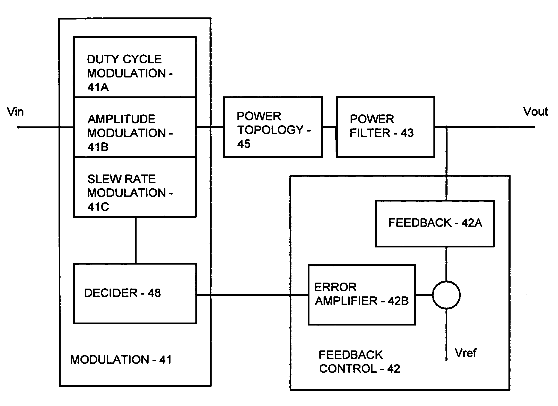
[0023] The present invention discloses a novel voltage or current regulator permitting better control and better performance. The voltage / current regulator according to the present invention is an integrated circuit voltage / current regulator comprising a switching regulation and an additional regulation mechanism. The two mechanisms are integrated in chip level circuitry, thus providing smaller area, faster response, and other benefits such as waveform control and voltage / current regulation control that are not available in board level combination. The additional regulation mechanism can be an amplitude modulation to modulate the input voltage / current, a slew rate modulation to modulate the slopes (rising slope and / or falling slope) of the switching output voltage / current, or a combination of amplitude modulation and slew rate modulation.

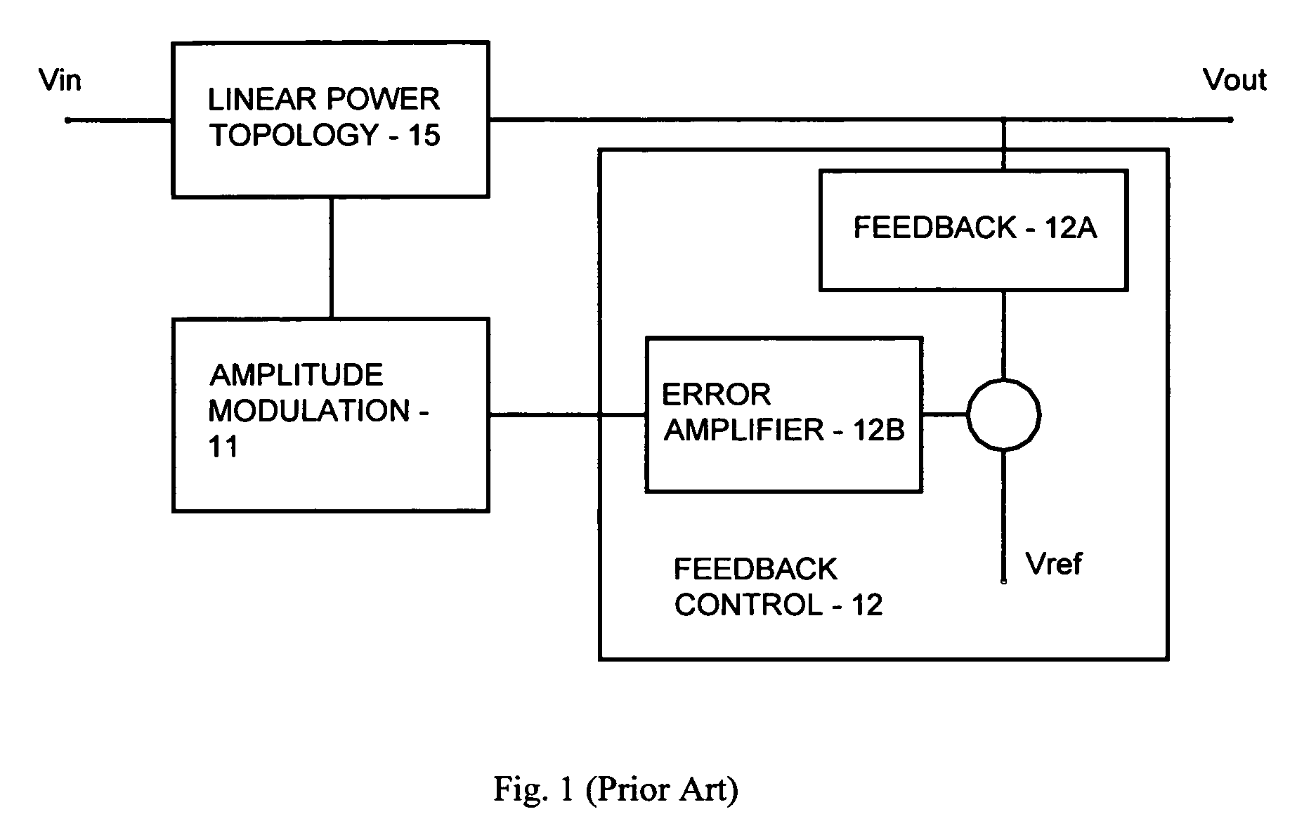
[0024]FIG. 1 shows a prior art block diagram of a linear voltage regulator, comprising an amplitude modulation block 11 which is controlled by a c...


PUM


Abstract

The present invention discloses an integrated voltage regulator comprising a switching regulation and an additional regulation mechanism. The additional regulation mechanism permits better control of the voltage regulator to enable improved performance. The present invention integrated voltage regulator provides an output voltage Vout in the formVout=(Vināˆ’Vamp)*(Duty Cycle)āˆ’Vslewwhere the additional regulation mechanism comprises an amplitude modulation Vamp to modulate the input voltage Vin, a slew rate modulation Vslew to modulate the output voltage Vout, or a combination of amplitude modulation and slew rate modulation.

Description

[0001] This application claims priority from U.S. provisional applications Ser. No. 60 / 790,687, filed Apr. 10, 2006, entitled ā€œAdaptive DC to DC Converter Systemā€, which is incorporated herein by reference. [0002] This application is related to co-pending applications Ser. No. ______, entitled ā€œAdaptive DC to DC Converter Systemā€ of the same inventor.BACKGROUND OF THE INVENTION [0003] Advances in electronic technology require a highly regulated voltage supply, regardless of the fluctuation in loads or input power sources. The two fundamental techniques to produce regulated voltage are linear voltage regulator and switching voltage regulator. Linear voltage regulators are typically an amplitude modulation circuit in which the amplitude of the input unregulated voltage is modulated to achieve the constant output voltage. Switching voltage regulators typically employ a duty cycle modulation circuit in which the duty cycle (the percent of the circuit ON time) of the unregulated voltage ...

Claims


Application Information

Patent Timeline
11 Oct 2007
Publication
US20070236193A1
IPC
G05F1/00
CPC
H02M3/157; H02M2001/0045; H02M2001/0029; H02M3/33515; H02M1/0029; H02M1/0045
Inventors
VO, HAI HUU