Airspeed / wind speed measurement device for aircraft, and display device for same

a technology of airspeed/wind speed and measurement device, which is applied in the direction of navigation instruments, instruments, and using reradiation, etc., can solve the problems of limited wind speed which can be measured by the device, danger of going beyond the speed restrictions, and difficulty in judging the speed in this way, so as to improve the safety and task completion rate, improve the measurement accuracy of the device, and improve the effect of accuracy

Inactive Publication Date: 2007-10-11
JAPAN AEROSPACE EXPLORATION AGENCY +1
View PDF17 Cites 22 Cited by
  • Summary
  • Abstract
  • Description
  • Claims
  • Application Information

AI Technical Summary

Benefits of technology

[0018] Moreover, since the measurement system for an aircraft according to the present invention comprises means for obtaining information relating to the attitude angles, the attitude angular velocities, and the ground speed of the aircraft during measurement, from the inertial data measurement device, and for correcting the measurement values from the Doppler anemometer by means of the information, then it is possible to correct error, even if cases where the aircraft performs unsteady movements, and it is also possible to improve the measurement accuracy of the device.
[0019] Furthermore, since the measurement system for an aircraft according to the present invention comprises means for obtaining positional information of the aircraft during measurement from the inertial data measurement device, and for correcting the measurement values from the Doppler anemometer by means of the information, it is possible to correct error, even in cases where the aircraft is moving at high speed, and hence the measurement accuracy of the device can be improved.
[0020] Moreover, since the display system for an aircraft according to the present invention displays the two-axis airspeed of the aircraft in a horizontal plane, the three-axis components of the wind speed currently encountered by the aircraft, and information on the wind speed distribution ahead of the aircraft, as measured by a Doppler anemometer, simultaneously in real time, then the measurement information can be recognized readily by the pilot, thus making a contribution to improvement in safety and task completion rates.
[0021] Furthermore, since the display system for an aircraft according to the present invention displays the two-axis airspeed of the aircraft in a horizontal plane in the form of bars, which respectively indicate the fore / aft direction speed component and the left / right direction speed component, on two-dimensional coordinates in which the vertical axis represents the speed in the fore / aft direction and the horizontal axis represents the speed in the left / right direction, then the current airspeed can be seen by the pilot at a glance, and furthermore, since a speed restriction area is displayed as a rectangle on the two-dimensional coordinates, then it is possible to prevent the aircraft from traveling at a speed exceeding these restrictions (in particular, in the lateral speed and rearward speed), thus making a contribution to improvement in safety and task completion rates.
[0022] Moreover, since the display system for an aircraft according to the present invention displays the three-axis components of the wind speed currently encountered by the aircraft by representing the wind speed information in the horizontal plane by numerical values as well as by the direction and thickness of an arrow, in terms of the wind direction and wind speed, and by representing the vertical wind speed information by numerical values as well as by a rectangular bar graph, in terms of the orientation in the vertical direction and the wind speed, then it is possible for the pilot readily to recognize the three-dimensional state of the wind currently encountered by the aircraft, thus assisting the pilot in performing suitable flight controls against wind turbulence, and hence contributing to improvement in safety and task completion rates.
[0023] Furthermore, since the display system for an aircraft according to the present invention displays the information on the wind speed distribution in the region ahead of the aircraft nose in which the beam is irradiated, by varying the color of the display continuously in accordance with the wind speed, using a blue color for a head wind component with respect to the aircraft, a green color for a windless state, and a red color for a tail wind component, and since it displays the wind speed distribution in the region ahead of the aircraft in a fan shape, separately for a horizontal plane and a vertical plane, then the state of the wind speed distribution ahead of the aircraft can be recognized readily, thus assisting the pilot in flying so as to avoid areas of strong wind turbulence, and hence contributing to improvement in safety and task completion rates.

Problems solved by technology

However, a conventional type of airspeed sensor, based on a Pitôt tube system (pressure measurement sensor), is not capable of measuring lateral speed or rearward speed, and therefore, although the pilot can judge the speed of the aircraft on the basis of the relative movement of the ground terrain, and the handling characteristics of the aircraft, it is difficult to judge the speed in this way in bad weather conditions, or at night time, when the terrain is difficult to see, or when the aircraft is over the sea, where there are few objects that serve as indicators.
Hence, there is a danger of going beyond the speed restrictions.
However, the wind speed which can be measured by this device is limited to a one-axis component in the direction of irradiation of the beam.
However, the system for measuring the three-axis components of the wind speed ahead of the aircraft by means of a lidar anemometer of this kind does not consider the use of information on the airspeed of the aircraft.
Moreover, there is no compensation for the movement of the aircraft during laser beam scanning, and hence there is a problem in that the error becomes large when the aircraft is moving in an unsteady fashion, or moving at high-speed.
In addition, the display of the obtained wind speed information is restricted to a display of the wind conditions ahead of the aircraft, with respect to a passenger aircraft which does not vary flight path largely.
However, in the case of a helicopter, there may be large vertical or lateral changes in the flight path when traveling at low speed, and therefore, the wind speed information in the vertical and lateral directions is also required, in addition to information on the wind speed in the forward direction of the aircraft.
However, it does not provide compensation for the movement of the aircraft during scanning, and therefore has large error when the aircraft is performing unsteady movements or traveling at high speed.
Moreover, the laser beam is irradiated in an upward lateral direction from the aircraft, and there is a problem in that the wind speed ahead of the aircraft cannot be measured.
Furthermore, no compensation is provided in respect of the movement of the aircraft during the travel of the beam of the lidar anemometer, and the error becomes large when the aircraft performs unsteady movement or travels at high speed.

Method used


Image

  • Airspeed / wind speed measurement device for aircraft, and display device for same
  • Airspeed / wind speed measurement device for aircraft, and display device for same
  • Airspeed / wind speed measurement device for aircraft, and display device for same

Examples


first embodiment

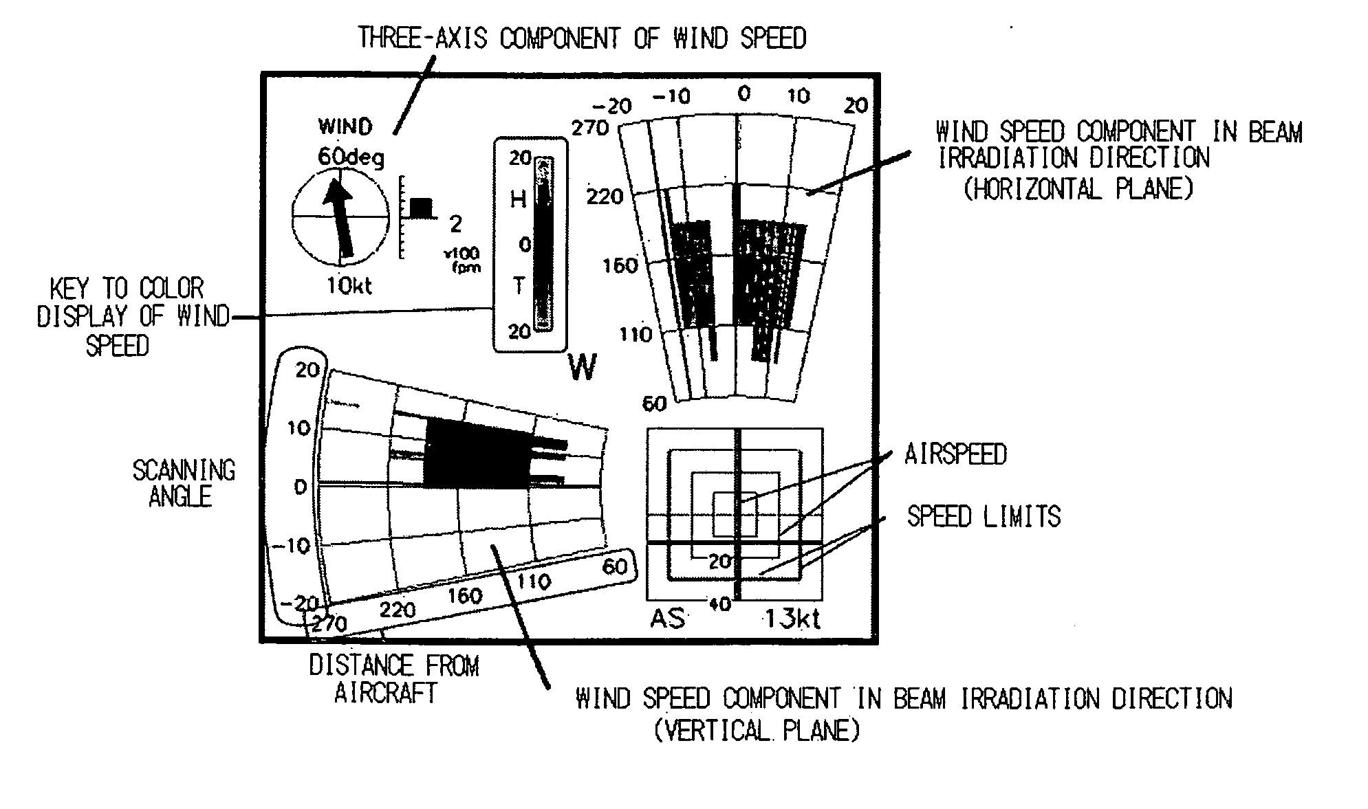
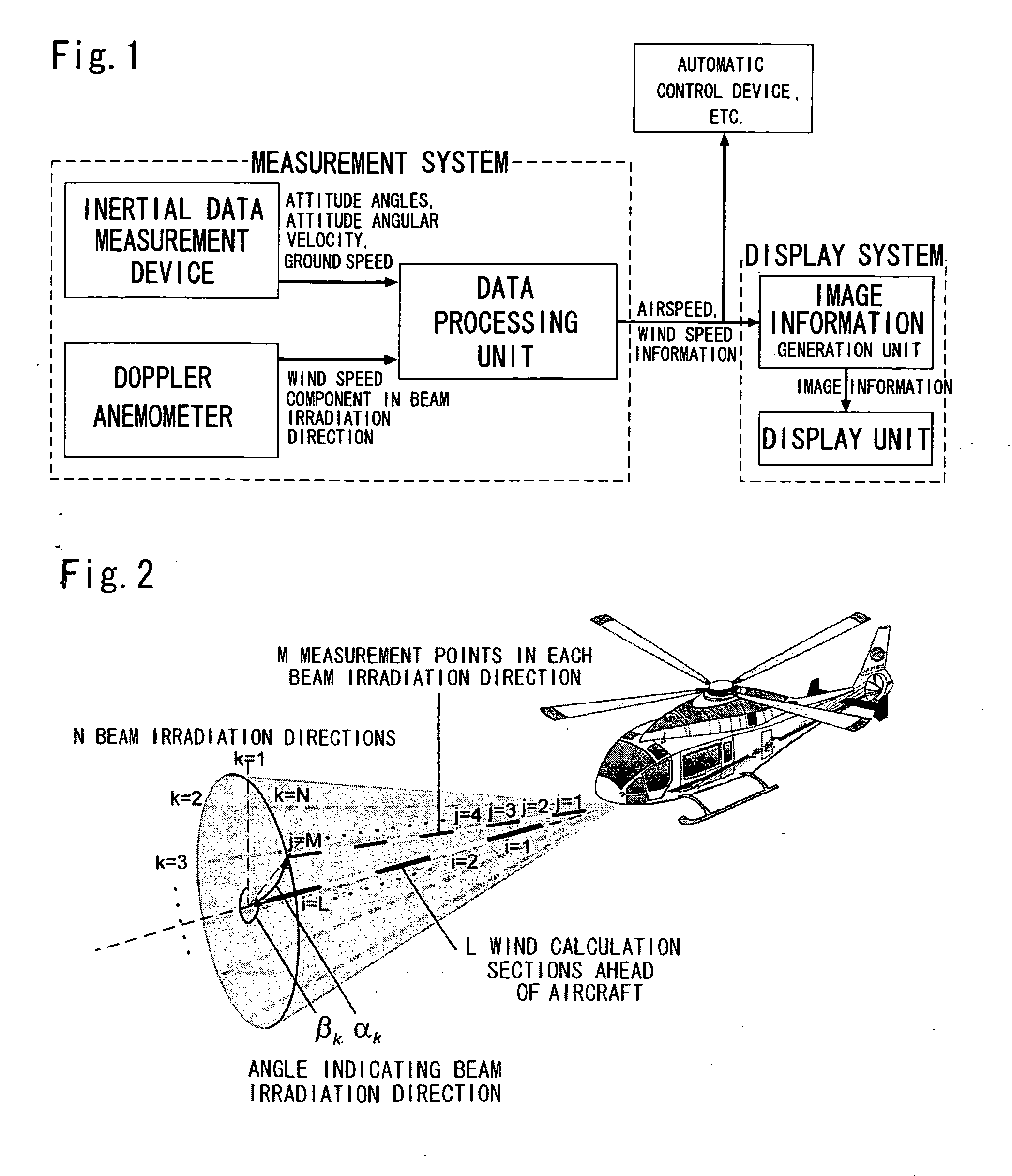
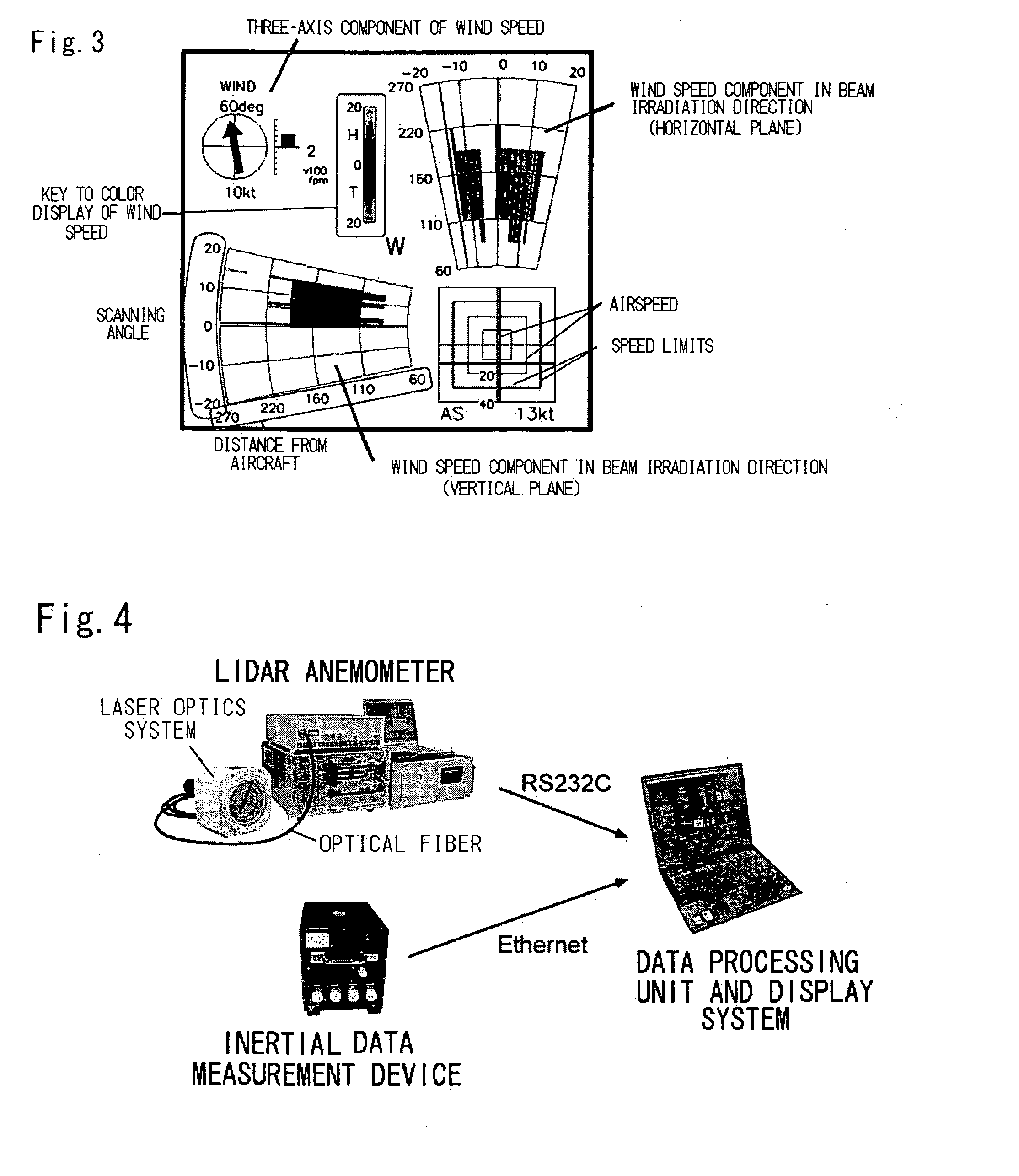
[0057]FIG. 4 shows an example of a trial manufacture of the present device. In order to facilitate the installation of the lidar anemometer on the aircraft, the laser optics system which needs to be fitted outside the aircraft is formed as a separate unit, and this optics system is connected to the main body of the anemometer by means of optical fibers. The inertial data measurement device comprises a three-axis gyro and accelerometer, and it is capable of measuring the attitude angles, attitude angular velocities and ground speed, which are required in order to compensate for the movement of the aircraft. The algorithms of the data processing unit and the image information generating unit are installed in a notebook computer. However, since the present embodiment relates to a helicopter which has a slow speed of movement, then the information on the position of the aircraft is not used in the compensation procedure (namely, the element “E(Φ,Θ,Ψ)rnedk” in Formula (1) is set to zero)...


PUM


Abstract

In the measurement system for an aircraft according to the present invention, the three-axis components of the airspeed of the aircraft, the three-axis components of the wind speed currently encountered by the aircraft, and the wind speed distribution ahead of the aircraft, are measured simultaneously, by providing a Doppler anemometer which measures the airflow speeds at a plurality of points separated by a prescribed distance in the beam irradiation direction, and an inertial data measurement device which measures the movement information and positional information of the aircraft. Furthermore, in the measurement system for an aircraft according to the present invention, the measurement accuracy of the device is improved by providing means for obtaining information the movement and positional information of the aircraft during measurement, from the inertial data measurement device, and for correcting the measurement values from the Doppler anemometer by means of the information.

Description

BACKGROUND OF THE INVENTION [0001] 1. Field of the Invention [0002] The present invention relates to a system which prevents an aircraft, such as a helicopter, from traveling at a speed exceeding a limit (and in particular, a lateral speed in the rightward or leftward directions, or a rearward speed), as well as assisting in flying the helicopter so as to avoid areas of strong wind turbulence, by simultaneously measuring the three-axis components of the airspeed of the aircraft, and the three-axis components of the wind speed ahead of the aircraft, and displaying or presenting this information to the pilot or the automatic control system controlling the aircraft. [0003] 2. Description of the Related Art [0004] In many cases, when a helicopter is stationary in the air (hovering), then although it has a capability for traveling sideways or rearwards, restrictions are placed on the speed of this travel (lateral speed in left or rightward direction, rearward speed) due to the flight cha...

Claims


Application Information

Patent Timeline
Patent Type & Authority Applications(United States)
IPC IPC(8): G01C23/00
CPCG01P5/26G01S17/95G01S17/58G01P13/025Y02A90/10
Inventor MATAYOSHI, NAOKIASAKA, KIMIOOKUNO, YOSHINORIHAGIO, MASAHIROHIRANO, YOSHIHITOKAMEYAMA, SHUMPEIANDO, TOSHIYUKIKIYOSUE, HIDETAKAFURUTA, MASASHIMATSUDA, TOMOYA
Owner JAPAN AEROSPACE EXPLORATION AGENCY
Why Eureka
Try Eureka