
Liquid Crystal Display Device

a display device and liquid crystal technology, applied in mechanical devices, lighting and heating apparatus, instruments, etc., can solve the problems of reduced light emission efficiency, reduced heat radiation and light emission, and increased operation temperature, and achieves easy treatment and high reliability.

Active Publication Date: 2007-10-11
PANASONIC LIQUID CRYSTAL DISPLAY CO LTD
View PDF6 Cites 34 Cited by
  • Summary
  • Abstract
  • Description
  • Claims
  • Application Information

AI Technical Summary

Benefits of technology

[0008]However, when a plurality of LEDs is used as a backlight to increase brightness, an operation temperature increases and light emission efficiency deteriorates. Accordingly, a metal plate and the like are used in consideration of heat radiation. Since it is difficult to form a heat radiation member on the light emission surface of the LED, the structure is restricted in view of the heat radiation and light emission. In addition, since the handling in the manufacturing process is difficult, the reliability of the structure is reduced.
[0009]Accordingly, the present invention is contrived to solve the above-mentioned problems. An object of the invention is to provide a liquid crystal display device that includes a backlight and a light source with high reliability and that can be easily handled in the manufacturing process in view of the heat radiation of the backlight.
[0013]According to the present invention, in a liquid crystal display device using a light-emitting element as a light source, it is possible to realize a liquid crystal display device including a light source which is easily treated and has high reliability.

Problems solved by technology

However, when a plurality of LEDs is used as a backlight to increase brightness, an operation temperature increases and light emission efficiency deteriorates.
Since it is difficult to form a heat radiation member on the light emission surface of the LED, the structure is restricted in view of the heat radiation and light emission.
In addition, since the handling in the manufacturing process is difficult, the reliability of the structure is reduced.

Method used


Image

  • Liquid Crystal Display Device
  • Liquid Crystal Display Device
  • Liquid Crystal Display Device

Examples


first embodiment

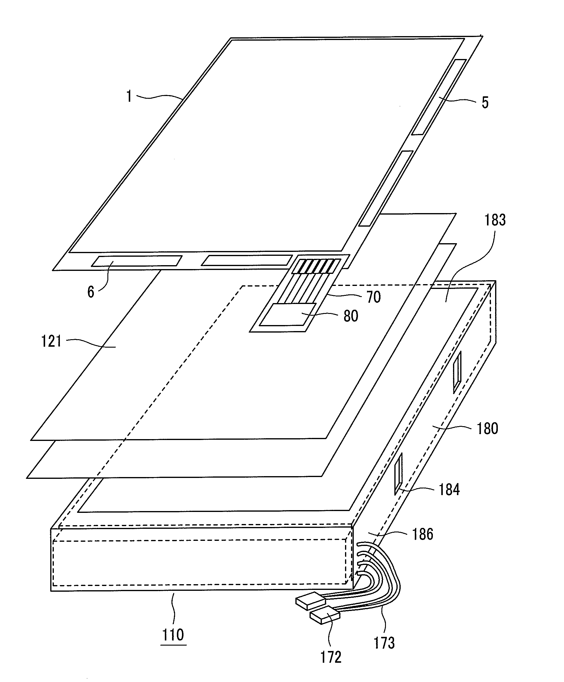
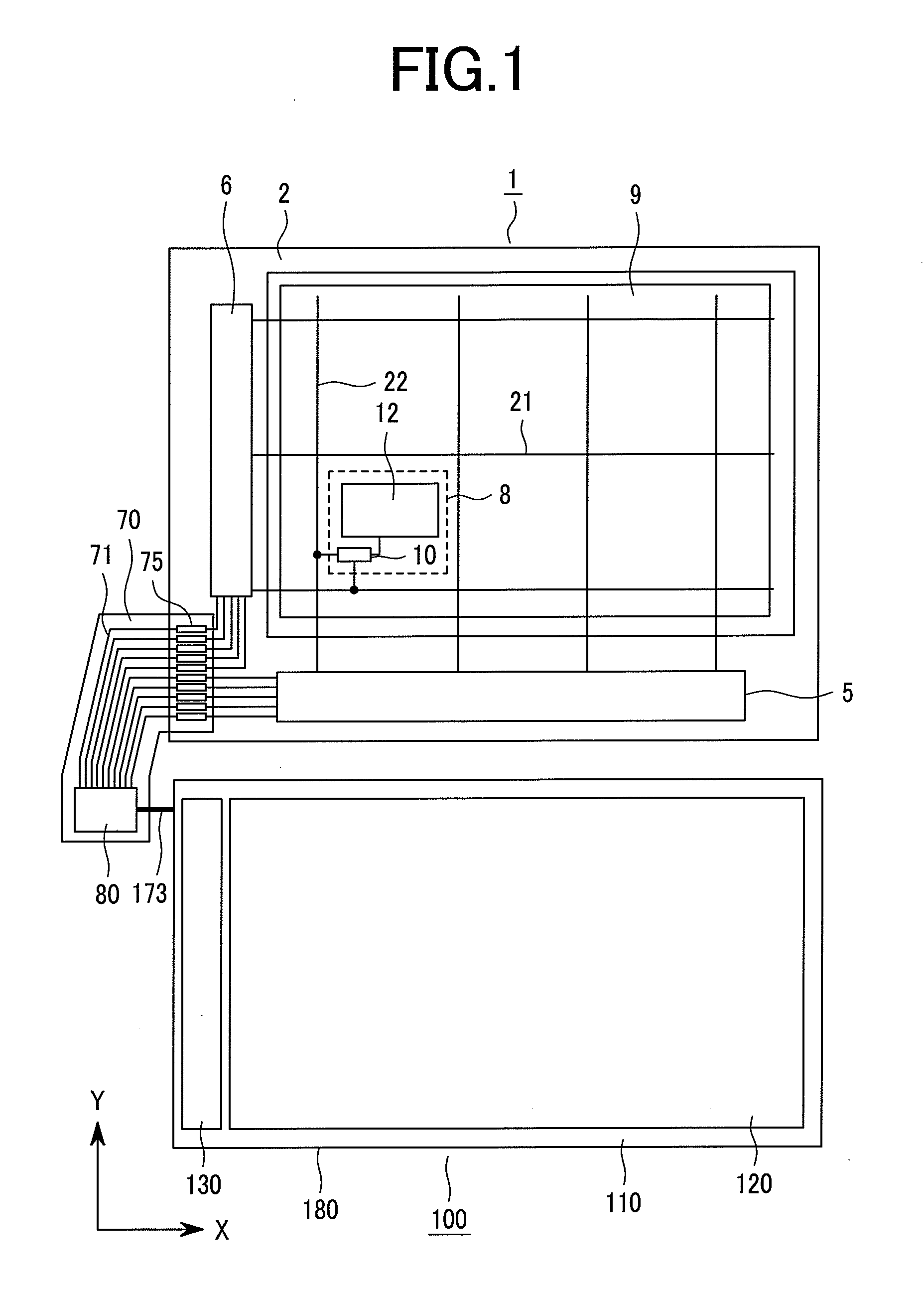
[0031]FIG. 1 is a plan view showing the whole configuration of a liquid crystal display device according to an embodiment of the present invention. In FIG. 1, the liquid crystal display device 100 includes a liquid crystal display panel 1, a backlight 110 and a control circuit 80. The liquid crystal display panel 1 is formed by sealing a liquid crystal layer between glass substrates having electrodes for forming pixels. A signal and power supply voltage, which are necessary for the display of the liquid crystal display panel 1, are supplied from the control circuit 80 to the liquid crystal display panel 1. The control circuit 80 is mounted on a flexible substrate 70, and a control signal is supplied to the liquid crystal display panel 1 through interconnections 71 and terminals 75.

[0032]The backlight 110 includes a light guide plate 120, a light source 130 and a receiving case 180. The backlight 110 is provided for the purpose of irradiating light to the liquid crystal display panel...


PUM


Abstract

The present invention provides a liquid crystal display device having a linear light source, which is easily treated, in consideration of the heat radiation of a light-emitting diode in the liquid crystal display using the light-emitting diode as a light source.A light-emitting diode 150 is provided on a metal substrate 161. The metal substrate 161 is formed in a case shape such that the heat generated at the light-emitting diode 150 received in the case is efficiently radiated. A resin material 175 is filled in the metal case to form a plate-shaped light source 130. It is possible to improve reliability during the handling in the manufacturing process by filling the resin material 175 to form the plate-shaped light source. It is possible to improve heat radiation effect by filling the resin material 157.

Description

CLAIM OF PRIORITY[0001]The present application claims priority from Japanese Application JP 2006-107315 filed on Apr. 10, 2006, the content of which is hereby incorporated by reference into this application.BACKGROUND OF THE INVENTION [0002]1. Field of the Invention[0003]The present invention relates to a light source of a non-self light emission type display device, and more particularly to a liquid crystal display device having a backlight using a light-emitting device as a light source.[0004]2. Description of the Related Art[0005]Recently, a liquid crystal display device is widely used as a display device. In particular, the liquid crystal display device is of a thin type having a small thickness with light weight and low power consumption, and thus is used as a display unit of a mobile apparatus.[0006]However, since the liquid crystal display is not of the self light emission type, light irradiation means is required. In general, as the light irradiation device used in the liqui...

Claims


Application Information

Patent Timeline
IPC IPC(8): G02F1/1335F21S2/00F21V8/00F21Y101/02G02F1/1333G02F1/13357
CPCG02B6/0073G02B6/0083G02B6/0085G02B6/0068G02F1/133615G02F2001/133628G02F1/133603G02F1/133628
Inventor KOGANEZAWA, NOBUYUKI
Owner PANASONIC LIQUID CRYSTAL DISPLAY CO LTD
Learn More