Auto exposure measurement system for an x-ray digital image capturer

a digital image capturer and exposure measurement technology, applied in the field of digital xray systems, can solve the problems of film cost, system efficiency reduction, film-based x-ray systems, etc., and achieve the effects of maximizing the light path, reducing the size of the x-ray imaging system, and maximizing the collection of emitted ligh

Inactive Publication Date: 2007-10-11
IMASCOPE INC
View PDF21 Cites 1 Cited by
  • Summary
  • Abstract
  • Description
  • Claims
  • Application Information

AI Technical Summary

Benefits of technology

[0017] It is an object of the present invention to obviate or mitigate the disadvantages of previous digital x-ray systems. In particular, it is an object of the invention to maximize the collection of emitted light while reducing the size of the x-ray imaging system. It is a further object of the present invention to maximize the light path between the intensifying screen and the lens assembly while maintaining image quality of optical designs with similar applications.

Problems solved by technology

Thus, the loss of X-rays reduces the efficiency of the system.
The disadvantages of film-based x-ray systems include film cost, chemical developer cost, exclusive use of a room as a dark room (or the purchase of an automatic film processor), and single master copy of the image.
Of course, this leads to further disadvantages such as storage for the film and chemicals, proper disposal for used film and chemicals, and careful packaging and mailing of the single image copy to other experts when further assessment is required.
Although the digital imaging process is significantly faster and solves many of the disadvantages inherent with film based systems, presently available digital filmless x-ray systems provide image quality inferior to those of film-based x-ray systems or high-quality systems at a prohibitive cost for private clinics.
In addition the electronic circuits of the CCD and those coupled to the CCD can be damaged by X-rays that pass through the working surface.
This usually leads to increased size of the CCD sensor and associated optics assembly to facilitate the optical design and improve system performance, hence increased system costs and size.
Unfortunately, to collect as much light as possible, it is imperative to position the lens assembly as close to the screen as possible, or use very large lenses.
The resulting image distortions are significant and limit the usefulness of this technique.
Furthermore, the lens design prevents the light from being evenly distributed, and more light is collected at the center of the screen than at the edges.
However any distortion in the source images will increase the complexity of aligning the images together.
Complex DSP programs and CCD alignment procedures are therefore required to minimize alignment problems, but undesired artifacts may be created.
This, of course, has also the disadvantage of increasing the system cost.
Another limitation of prior art digital X-ray imaging systems is the inconsistent image quality over the intensifying screen.
As the CCD is brought closer to the intensifying screen, thus increasing the viewing angle, image sharpness is lost since the light energy is dispersed over several pixels, especially at the edges of the image.
Therefore, inconsistent quality across the image is obtained, even though relatively large amounts of light may be collected.
This effect limits quality image capture to a smaller area of the intensifying screen.

Method used


Image

  • Auto exposure measurement system for an x-ray digital image capturer
  • Auto exposure measurement system for an x-ray digital image capturer
  • Auto exposure measurement system for an x-ray digital image capturer

Examples


Embodiment Construction

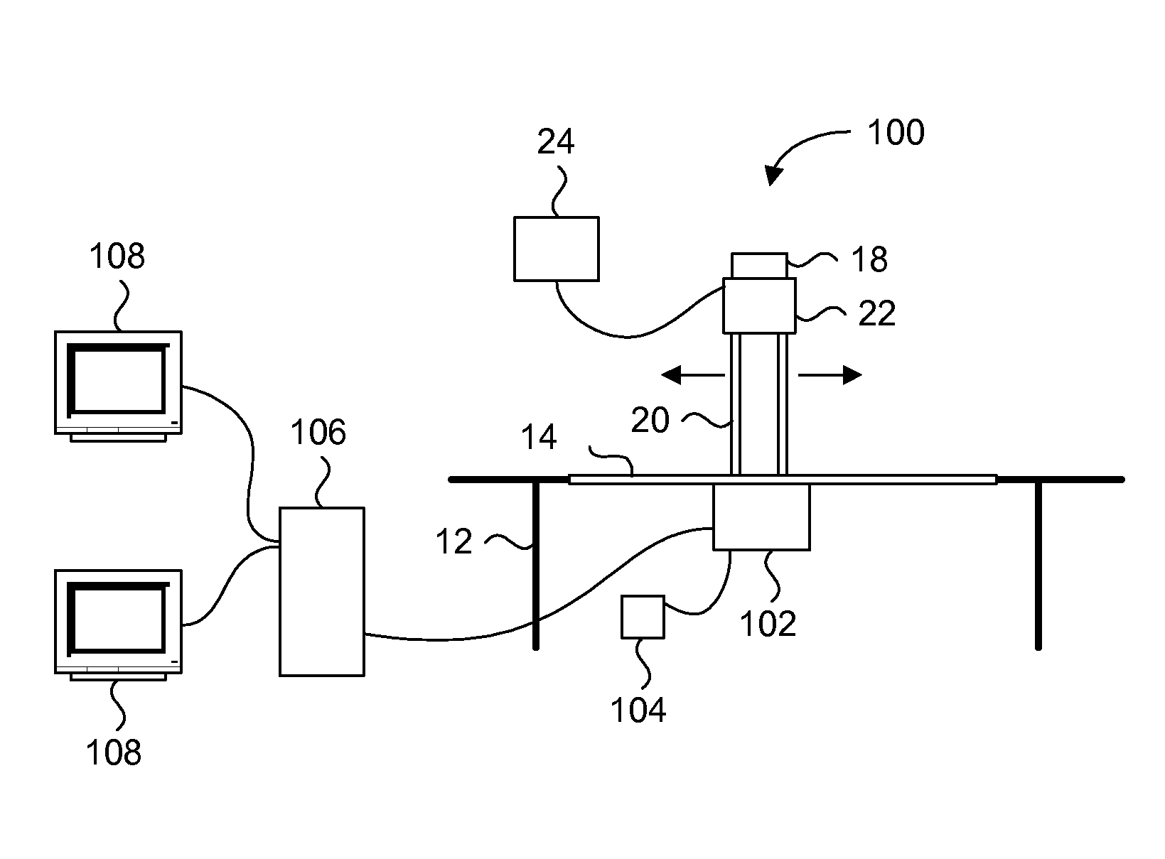
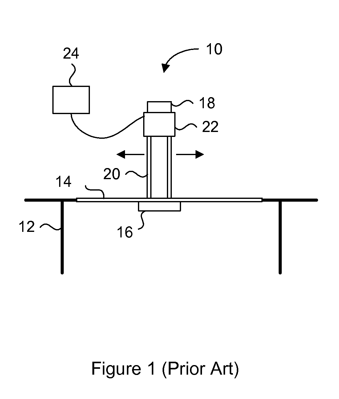
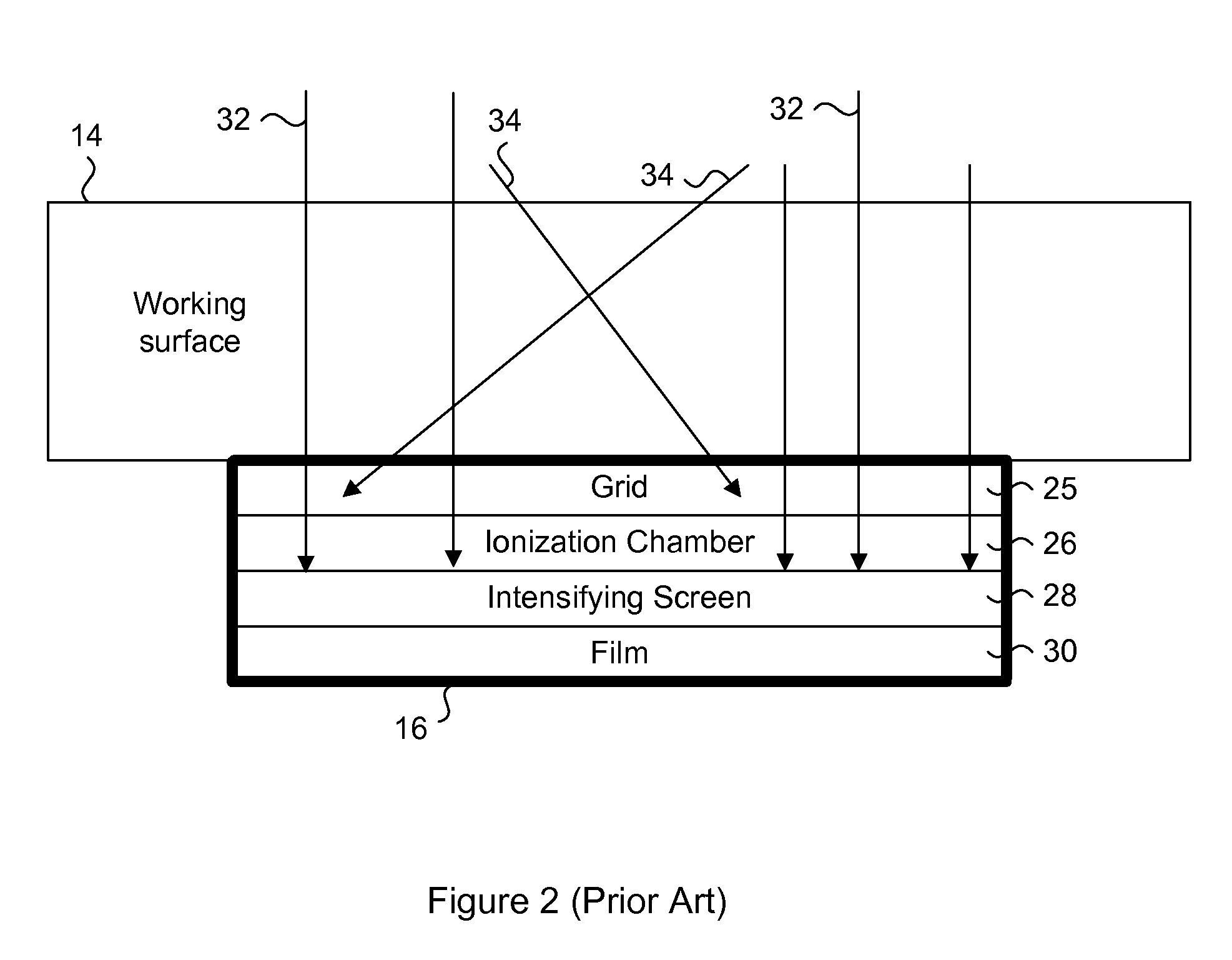
[0029] Generally, the present invention provides a digital X-ray system for capturing high quality images by maximizing the collection of emitted light from an intensifying screen in response to X-ray impact. The digital X-ray system includes a housing having an intensifying screen for receiving emitted X-rays and a combination of two planar reflectors for optimizing the light path between the intensifying screen and the lens assembly. A CCD chip receives the light from the lens assembly, to provide a digital image for immediate on-board processing or post-processing by a computer. The housing is compact, and can be used as a direct replacement for traditional film cartridges without major modifications to the system. The lens assembly includes freeform matched lenses to remove any optical distortions, and the housing includes a light sensor for providing exposure measurement and feedback. The system is designed to be quasi-monochromatic to maintain consistent image quality over the...


PUM

PropertyMeasurementUnit
thicknessaaaaaaaaaa
distanceaaaaaaaaaa
sizeaaaaaaaaaa

Abstract

A digital X-ray system for capturing high quality images by maximizing the collection of emitted light from an intensifying screen in response to X-ray impact. The digital X-ray system includes a housing having a fluorescent intensifying screen for receiving emitted X-rays, two reflectors for maximizing light collection and optimizing the light path from the intensifying screen, and a lens assembly. A CCD chip receives the light from the lens assembly, to provide a digital image for immediate on-board processing or post- processing by a computer. The housing is compact, and can be used as a direct replacement for traditional film cartridges without major modifications to the system. The lens assembly includes freeform matched lenses to remove optical distortions, and the housing includes a light sensor for providing exposure measurement and feedback. The system is designed to be quasi-monochromatic to maintain consistent image quality over the entire area of the intensifying screen.

Description

RELATED APPLICATION [0001] The present application is a divisional of U.S. patent application Ser. No. 11 / 000,533, filed Dec. 1, 2004, which is incorporated herein by reference.FIELD OF THE INVENTION [0002] The present invention relates generally to digital X-Ray systems. In particular, the present invention relates to light collection apparatus for digital X-Ray systems. BACKGROUND OF THE INVENTION [0003] X-ray systems are commonly used in medical applications to provide intrusive-free visual assessment of tissues and bones. Such systems are commonly found in hospitals, clinics and even veterinarian clinics to assist doctors in diagnosing problems with their patients. [0004] Conventional X-ray systems use films exposed to an intensifying screen (also known as a phosphorous screen or fluorescent screen). This screen converts the high-energy photons (X-rays) that reach the screen into lower energy photons (typically visible light), which then imprints the object being exposed onto a ...

Claims


Application Information

Patent Timeline
Patent Type & Authority Applications(United States)
IPC IPC(8): H05G1/64A61B6/00C08L35/00C09J7/02C09J133/08C09J153/00G01T1/164G01T1/20H04N5/225H04N5/321
CPCA61B6/00A61B6/4233A61B6/4488G01N23/04A61B6/508H04N5/2254H04N5/32H04N5/321A61B6/4291G01T1/1642
Inventor CASEAULT, JEAN
Owner IMASCOPE INC
Why Eureka
Try Eureka